This is an old revision of the document!
Table of Contents
Master Control Port Boot time I/O (ADAU145x)
The master control port I/O block allows communication with one external device during DSP program initialization. Typically this block is used to configure an external device like a converter or codec. Communication (read or write) over the master control port bus (I2C or SPI) occurs only once at start-up of the DSP program, and prior to audio processing. The data transferred between host and device is defined in a SigmaStudio sequence file which can be generated using the SigmaStudio sequence window.
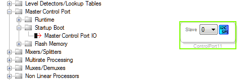
Configuration
Click on  to configure the parameters.
I2C configuration
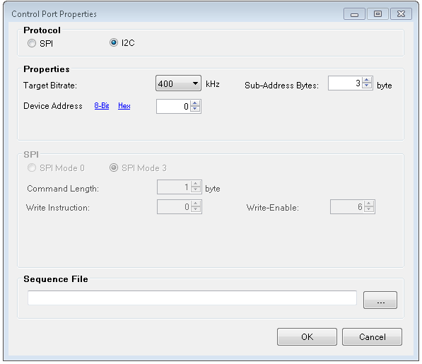
GUI Control
| GUI Control Name | Default Value | Range | Function Description |
|---|---|---|---|
| Bitrate | 400 kHz | 20 kHZ - 400 kHZ | I2C Speed |
| Device Address | 0 | 0 – 127 | I2C Slave Device Address |
| Sub-Address Bytes | 2 | 1-4 | Length of the sub address |
| Sequence file | - | - | Device write/read sequence to execute at boot time.This file can be defined and saved from SigmaStudio's sequence window. |
SPI configuration
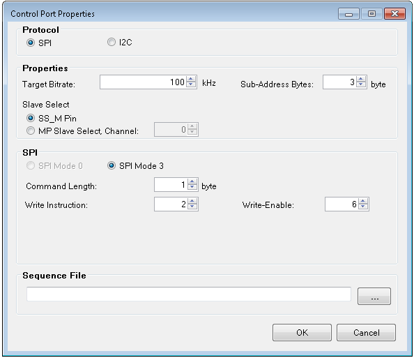
GUI Control
| GUI Control Name | Default Value | Range | Function Description |
|---|---|---|---|
| Bitrate | 100 kHz | 100 kHZ - 100000 kHZ | SPI Speed |
| SS_M Pin | 0 | 0 | SPI Slave Select Channel |
| MP Slave Select Channel | Disabled(enabled by click on radio button) | 0 - 7 | SPI Slave Select Channel |
| Sub-Address Bytes | 2 | 1-4 | Length of the sub address |
| Command Length | 1 | 1-4 | Length of the command sent in bytes |
| Write Instruction | 0 | 0-255 | Instruction value for a write operation (0x0 for ADI audio devices, typically 0x2 for eeprom/flash) |
| Write-Enable instruction | 6 | 0 - 255 | Instruction value for device write-enable operation (ignored for Master Control Port I/O Boot) |
Support for Multiple Slaves
Multiple external devices can be configured by creating multiple instances of the master control port boot time IO module and selecting appropriate slave select in the configuration parameters.
The sequence of booting up of different slaves can be configured by using the drop down list next to the image as shown below
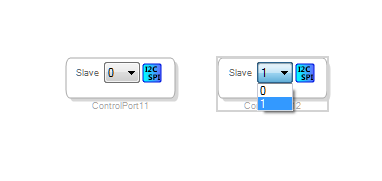
Support for Different SPI Slave Select Pins
If the device to be programmed is selected through MP0 (the /SS_M pin), no configuration is required in the register controls. Otherwise, the multipurpose pin must be configured to act as the slave select in the Register Window. (Hardware Configuration → ICx - ADAU145x Register Controls → MULTIPURPOSE/AUXADC)
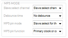
- Slave Select Channel → 'Slave Select Channel x'
- MPx pin mode → 'Slave Select for Master SPI port'
- MPx pin function → 'Multipurpose function'
The following table shows the mapping between module's parameter and the register control window.
Please note that for some other blocks, there is an offset of 1 between the module parameter and the register control window.
| 'Slave Select' in Configuration Window | 'Slave Select Channel' in the Register control |
|---|---|
| 0 | Slave Select Channel 0 |
| 1 | Slave Select Channel 1 |
| 2 | Slave Select Channel 2 |
| 3 | Slave Select Channel 3 |
| 4 | Slave Select Channel 4 |
| 5 | Slave Select Channel 5 |
Creating Sequence File for SPI/I2C slave not supported by SigmaStudio
Use the following file and edit for your slave.
- ADAU1361.xml
version="1.0" standalone="no"?>
Please follow the steps below to edit the XML for your Slave.
- Edit IC, IC_Address and Address_byte_length fields in xml. Please note that IC_Address should be an 8-bit I2C address in decimal format. Address_byte_length refers to the length, in bytes, of the external IC's address space.
IC="ADAU1361" IC_Address="112" Address_byte_length="2"> - Add your register writes as shown below.
instr="writeXbytes" len="8" addr="16386" ParamName="Reg2" DspName="IC 1"> 00 FD 00 0C 20 01>Please match all the fields as follows.
instr => "writeXBytes"
len => Data Length in bytes+ Address_byte_length
addr => Register Address in decimal (not hexadecimal)
Then the value part should have the register values in Hexadecimal. A space should separate each data as shown in the example. In this example len => 6 (data length) + 2 (Address_byte_length) = 8
- You can add delays as shown below.
instr="delay" ParamName="IC 1.Delay" DspName="IC 1"> 00 64>Delay is in milliseconds (Hexadecimal Format)
Supported ICs
- ADAU145x