This is an old revision of the document!
Zero Comparator
| The Zero Comparator block takes any input and compares the value to 0. If the input signal is non-zero, the output will be zero. If the input is zero, the output will be a flag of “1” in the bit position designated by the drop-down box. |  |
Input Pins
| Name | Format [int/dec] - [control/audio] | Function Description |
|---|---|---|
| Pin 0: Input | any - any | The input signal to compare to 0 |
Output Pins
| Name | Format [int/dec] - [control/audio] | Function Description |
|---|---|---|
| Pin 0: Output | int - control | The output signal of 0 or 1 in the designated bit position |
GUI Controls
| GUI Control Name | Default Value | Range | Function Description |
|---|---|---|---|
| Output Bit Designation | 28 | [28.0 Bit26] | Sets bit position of the output “1” flag. 28.0 is the default values which represents 1LSB. |
DSP Parameter Information
| GUI Control Name | Compiler Name | Function Description |
|---|---|---|
| Output Bit Designation | ZeroCompareAlg1output1 | Actual value written to DSP from the representation of the drop-down menu to select the bit position of the output “1” flag. |
Algorithm Description
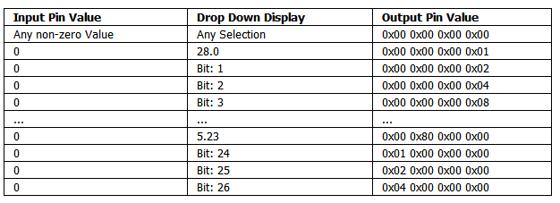
The following table shows what the data output value will be for given input values, based on the selection from the Drop Down Display.
Example
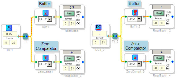
The following schematic image shows both the Buffer and the Zero Comparator for a non-zero and zero input. There results of the algorithm are captured in the DSP Readback cell.
Algorithm Details
| Toolbox Path | Basic DSP - Logic - Invert - Zero Comparator | |
| Cores Supported | ADAU144x ADAU176x ADAU178x ADAU170x AD1940 |
|
| “Grow Algorithm” Supported | yes - see Algorithm Growth Information | |
| “Add Algorithm” Supported | yes - see Algorithm Addition Information | |
| Subroutine/Loop Based | no | |
| Program RAM | 4* | |
| Data RAM | 1* | |
| Parameter RAM | 1* | |
*Numbers are based on one instance of the algorithm with no additional “add” or “grow”
Algorithm Growth Information
| Description | When the Zero Comparator algorithm is grown, a new pair of input/output pins is added to the control. The algorithm behavior is the same, and the drop-down menu selection applies to all the input signal comparisons. |  |
| Program RAM Repetition | 4 per growth | |
| Data RAM Repetition | 1 per growth | |
| Parameter RAM Repetition | 0 | |
Algorithm Addition Information
| Description | When the Buffer algorithm is added, a new control is stacked vertically. The newly added drop-down menu selection applies to the newly added input/output pair. | 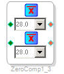 |
| Program RAM Repetition | 4 per add | |
| Data RAM Repetition | 1 per add | |
| Parameter RAM Repetition | 1 per add | |