This is an old revision of the document!
Hardware Configuration Tab
The Hardware Configuration workspace allows you to choose a Processor or Processors for your design. It also allows you set up communication between SigmaStudio and the hardware.
To learn about the advanced operations that can be accessed in the Hardware Configuration tab (including Output Capture, Flash/E2Prom download, Register Control Window, and the Register Read/Write Window), refer to the topics within the Hardware Windows section.
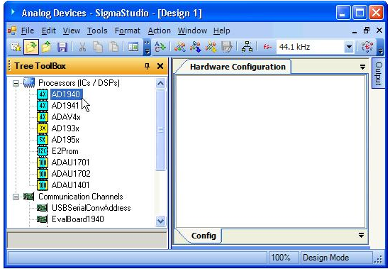
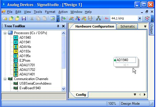
To insert a processor (IC/DSP) into your design:
- Select a “Processor” from the Toolbox with the left mouse button:
- Drag and Drop the processor block into the Hardware Configuration Window on the right:
To establish a connection between your DSP processor and hardware:
- Click the Communication Channels category (at the bottom of the Toolbox column).
- Select your evaluation board or USB device from the list and drag and drop it into the workspace.
- Connect the two blocks by drawing a wire between the communication channel and the processor block, blue colored diamond to green diamond. For a USB connection using AD1940, the cells in your workspace should look something like this:
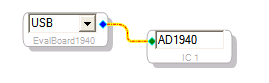
The color of the USB label on the communication block indicates whether a USB communication channel has been established. If you have properly configured the USB hardware, the background color will be light orange or white. If the communication is not initialized the background will be red. Note that this only indicates that a USB connection is active, it does not guarantee communication with the SigmaDSP IC or that the SigmaDSP hardware is properly configured.
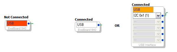
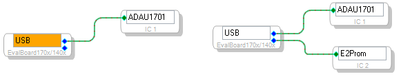
The “Connected” background color is white when all board ICs are connected, and orange when only some ICs are connected, but not all. For example the ADAU1701 evaluation board includes both an ADAU1701 IC and an E2Prom IC. When connecting only the ADAU1701 the background will be light orange, but it will be white when connecting both an ADAU1701 and an E2Prom IC.