Table of Contents
SPI Read (ADAU145X)
There are two different versions of the SPI Read module.
- SPI Periodic Read
- SPI Read with External Trigger
SPI Periodic Read
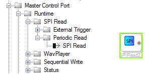
The 'SPI Periodic Read' block reads a particular sub address from any SPI slave periodically and sends the value read in the output pin.
Output Pins
| Name | Format [int/dec] - [control/audio] | Function Description |
|---|---|---|
| Pin 0: SPI Data | decimal - control | Outputs data read over SPI |
Configuration
Click on  to configure the parameters for SPI read.
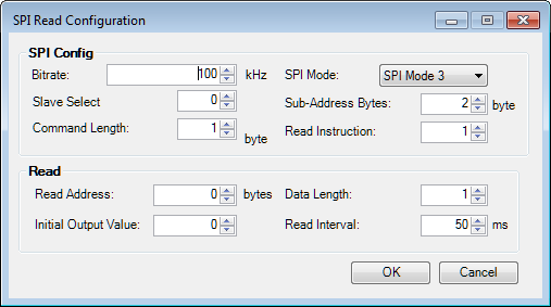
To monitor multiple registers in the same slave, create multiple instances of the cell.
Support for Different Slave Select
If the device to be programmed is selected through MP0 (the /SS_M pin), no configuration is required in the register controls. Otherwise, the multipurpose pin must be configured to act as the slave select in the Register Window. (Hardware Configuration → ICx - ADAU145x Register Controls → MULTIPURPOSE/AUXADC)
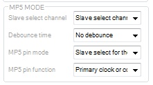
- Slave Select Channel → 'Slave Select Channel x'
- MPx pin mode → 'Slave Select for Master SPI port'
- MPx pin function → 'Multipurpose function'
The following table shows the mapping between the module's parameter and the register control window. Please note that for some other blocks, there is an offset of 1 between the module parameter and the register control window.
| 'Slave Select' in Configuration Window | 'Slave Select Channel' in the Register control |
|---|---|
| 0 | Slave Select Channel 0 |
| 1 | Slave Select Channel 1 |
| 2 | Slave Select Channel 2 |
| 3 | Slave Select Channel 3 |
| 4 | Slave Select Channel 4 |
| 5 | Slave Select Channel 5 |
GUI Control
| GUI Control Name | Default Value | Range | Function Description |
|---|---|---|---|
| Bitrate | 100 kHz | 100 kHZ - 100000 kHZ | SPI Speed |
| Slave Select | 0 | 0 – 6 | SPI Slave Select Channel |
| Mode | Mode 3 | Mode 0/ Mode 3 | SPI protocol mode |
| Data Length | 4 | 1-4 | Length of the data to be read |
| Sub-Address Bytes | 2 | 1-4 | Length of the sub address |
| Read Interval | 50 ms | 50 - 5000 ms | Interval between 2 consecutive SPI Read |
| Read Address | 0 | 0 to Pow(2, Address Length) - 1 | Address to be read from |
| Read Instruction | 1 | 0-255 | Instruction value for a read operation (0x1 for ADI audio devices, typically 0x3 for eeprom/flash) |
| Command Length | 1 | 1-4 | Length of the command sent in bytes |
| Initial Output Value | 0 | -2147483648 to 2147483647 | Value in the output pin till the first read is complete. |
DSP Parameter Information
| GUI Control Name | Compiler Name | Function Description |
|---|---|---|
| Bitrate | SPIPriodicReadAlg1spiSpeed | SPI Speed |
| Mode | SPIPriodicReadAlg1spiMode | SPI Protocol Mode |
| Slave Select | SPIPriodicReadAlg1slaveSelect | SPI Slave Select Channel |
| Read Address | SPIPriodicReadAlg1readAddress | Address to be read from |
| Sub-Address Bytes | SPIPriodicReadAlg1addressLength | Length of the sub address |
| Data Length | SPIPriodicReadAlg1dataLength | Length of the data to be read |
| Read Interval | SPIPriodicReadAlg1readInterval | Interval between 2 consecutive SPI Read |
| Command Length | SPIPriodicReadAlg1commandLength | Length of the command sent in bytes |
| Read Instruction | SPIPriodicReadAlg1readInstruction | Instruction value for a read operation (0x1 for ADI audio devices, typically 0x3 for eeprom/flash) |
Supported ICs
- ADAU145x
SPI Read with external Trigger
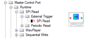
The 'SPI Read with external Trigger' block reads a particular sub address from any I2C slave when a rising edge is detected in the input pin.
Input Pins
| Name | Format [int/dec] - [control/audio] | Function Description |
|---|---|---|
| Pin 0: Trigger | decimal - control | Rising edge in this signal initiates read. |
Output Pins
| Name | Format [int/dec] - [control/audio] | Function Description |
|---|---|---|
| Pin 0: SPI Data | decimal - control | Outputs data read over SPI |
Configuration
Click on to configure the parameters for SPI read.
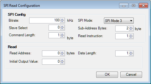
Create Multiple instances for monitoring multiple slaves/ multiple sub address from same slave.
Support for Different Slave Select
If the device to be programmed is selected through MP0 (the /SS_M pin), no configuration is required in the register controls. Otherwise, the multipurpose pin must be configured to act as the slave select in the Register Window. (Hardware Configuration → ICx - ADAU145x Register Controls → MULTIPURPOSE/AUXADC)
- Slave Select Channel → 'Slave Select Channel x'
- MPx pin mode → 'Slave Select for Master SPI port'
- MPx pin function → 'Multipurpose function'
The following table shows the mapping between module's parameter and the register control window.
| 'Slave Select' in Configuration Window | 'Slave Select Channel' in the Register control |
|---|---|
| 0 | Slave Select Channel 0 |
| 1 | Slave Select Channel 1 |
| 2 | Slave Select Channel 2 |
| 3 | Slave Select Channel 3 |
| 4 | Slave Select Channel 4 |
| 5 | Slave Select Channel 5 |
GUI Control
| GUI Control Name | Default Value | Range | Function Description |
|---|---|---|---|
| Bitrate | 100 kHz | 100 kHZ - 100000 kHZ | SPI Speed |
| Slave Select | 0 | 0 – 6 | SPI Slave Select Channel |
| Mode | Mode 3 | Mode 0/ Mode 3 | SPI protocol mode |
| Data Length | 4 | 1-4 | Length of the data to be read |
| Sub-Address Bytes | 2 | 1-4 | Length of the sub address |
| Read Address | 0 | 0 to Pow(2, Address Length) - 1 | Address to be read from |
| Read Instruction | 1 | 0-255 | Instruction value for a read operation (0x1 for ADI audio devices, typically 0x3 for eeprom/flash) |
| Command Length | 1 | 1-4 | Length of the command sent in bytes |
| Initial Output Value | 0 | -2147483648 to 2147483647 | Value in the output pin till the first read is complete. |
DSP Parameter Information
| GUI Control Name | Compiler Name | Function Description |
|---|---|---|
| Bitrate | SPIReadExtTriggerAlg1spiSpeed | SPI Speed |
| Mode | SPIReadExtTriggerAlg1spiMode | SPI Protocol Mode |
| Slave Select | SPIReadExtTriggerAlg1slaveSelect | SPI Slave Select Channel |
| Read Address | SPIReadExtTriggerAlg1readAddress | Address to be read from |
| Sub-Address Bytes | SPIReadExtTriggerAlg1addressLength | Length of the sub address |
| Data Length | SPIReadExtTriggerAlg1dataLength | Length of the data to be read |
| Command Length | SPIReadExtTriggerAlg1commandLength | Length of the command sent in bytes |
| Read Instruction | SPIReadExtTriggerAlg1readInstruction | Instruction value for a read operation (0x1 for ADI audio devices, typically 0x3 for eeprom/flash) |
Supported ICs
- ADAU145x