How to select filters using input as the controller?
Hi,
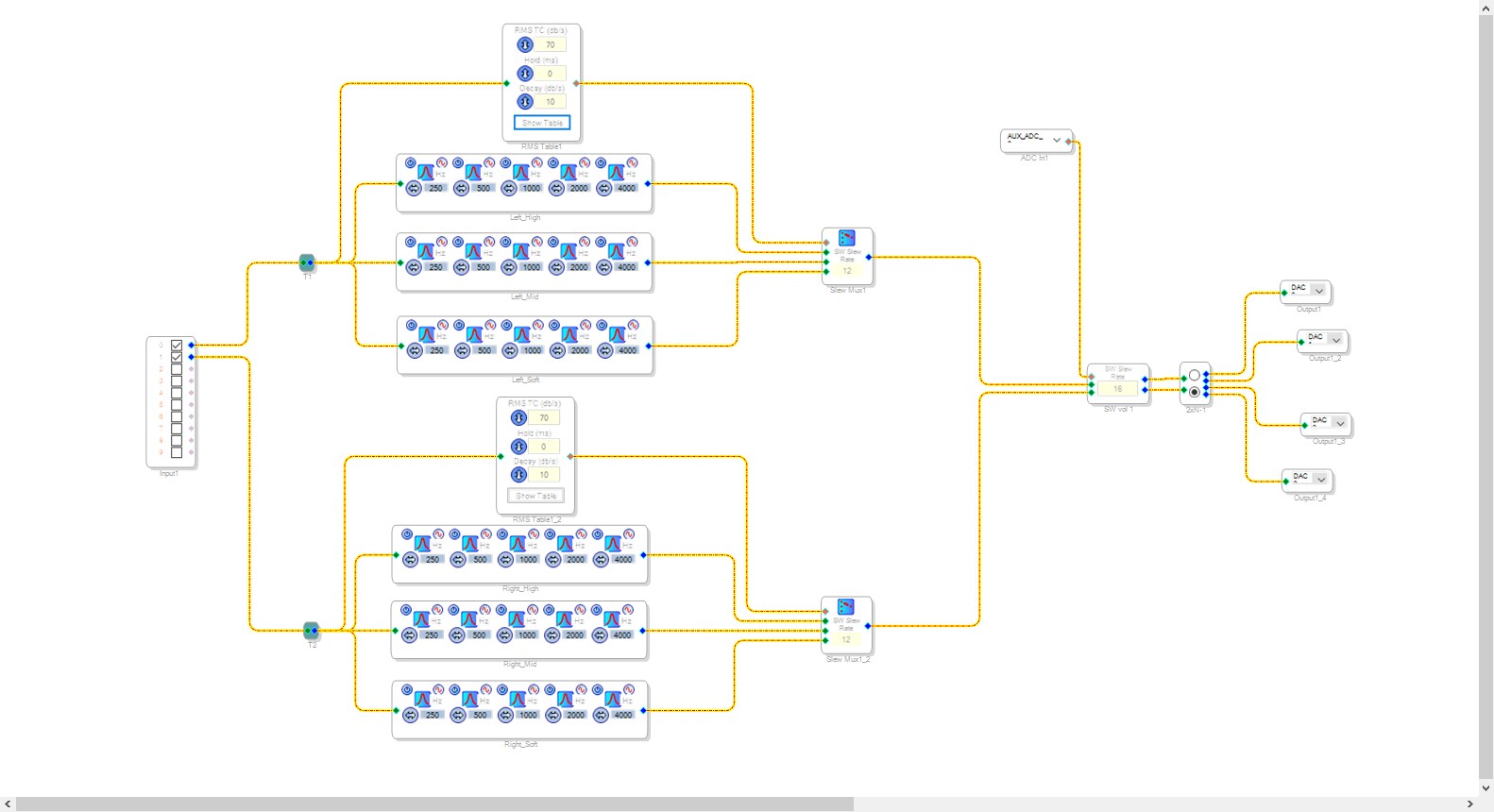
I'm working on a project where I need to switch the filters for different magnitude of input using ADAU 1701. Here is what I have so far:
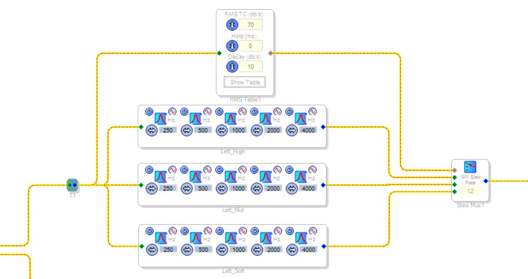
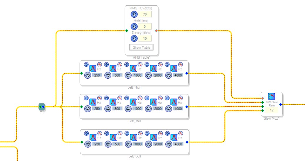
Zoom in to the upper part:
So I try to use the RMS lookup table to have the input mapped to a output index. Per se, when the rms LUT takes the signal between -30 ~ -50 dB. it will output an integer 1 to the mux and then the middle filter will be triggered, and inputs higher than -30 dB or lower than -50 dB will trigger the high or soft filter, respectively.
When I actually compile this code, there are no signal outputs from the chip. I think I've set the RMS LUT in a wrong way, but I'm not sure how to fix it. I'm now looking in adding a peak envelope before the RMS LUT block, but I'm not sure. Can you help me, or tell me what's wrong with this whole setup?
Thanks,
Joseph
dac output
adc analog input voltage
adau 1701
Hello Joseph,
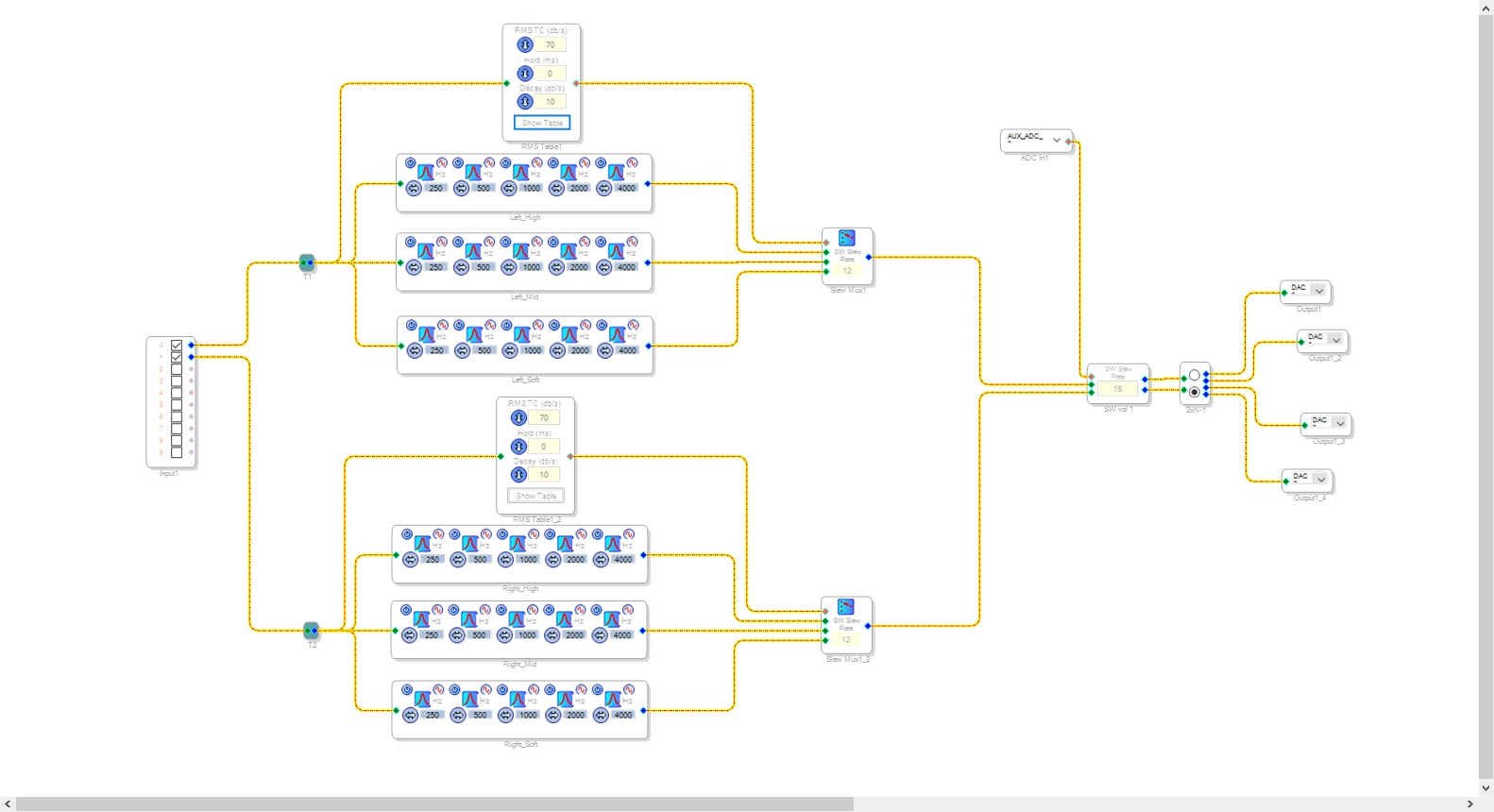
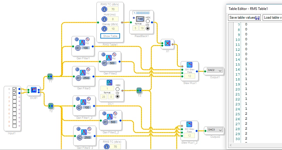
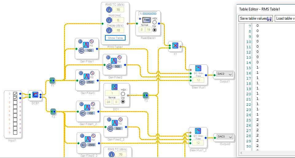
A simple modification makes your project fully functional. Just add the DC source and multipliers as shown below:
The RMS Lookup Table outputs a decimal, 5.23 format number (the same number format used by audio signals and such). 5.23 numbers have five binary bits before the binary point and 23 bits after. A "1" in this format appears inside the ADAU1701's registers as hexadecimal 08 00 00 00. Numbers in this format can drive control inputs for volume controls directly, but aren't suitable for index MUXes and index filters. Index blocks expect instead, an integer (28.0 format) input. A "1" in this format appears as 00 00 00 01. Thus we see that the lookup table's 5.23 numbers are way too huge for the MUX. An MUX usually goes silent for out-of-range inputs (but may provide unexpected results).
It's easy to convert a decimal format to integer -- just multiply the decimal number by an integer 1. For more info on number formats, see this FAQ -- What are the number formats for SigmaDSP?
Finally, there's more efficient ways to implement your sliding filter. Presently you've got 30 filters using 300 instructions. The un-selected filter banks continue to run yet contribute nothing to the result. Check out the Lookup (Index selectable) Filters in the toolbox. These come in several flavors, yet they all place essentially one set of filters in the audio path --swapping out their control coefficients instead of swapping entire filters. The more alternative response choices you wish to provide, the more instructions you'll save.
Hi Bob,
Thank you for your reply! It's really helpful. I did not know the RMS LUT output number format, and I thought it just map the number I input.
About the 300 instructions, I am a little bit lost. Do you mean every time the chip gets an input, it will go through all those filters all at once, and then choose one output from all the filter outputs? What would happen if there are too much instructions, like it will suck up the battery real fast?
About the ISF you mentioned, originally I was thinking about using the ISF instead of six filter banks, but in the ISF I could not find any filters with multiple amplifications on different frequencies. For example, if I need a filter that consists 5 band-past filters, and that's a selection, say "1", I could not do it in the ISF because each of the band-past filters are numbered from 0-4. Therefore when the control signal comes in, it would not do the 5 band-past filters set, but the number "1" band-past filter in the ISF right? I am not sure if I were doing it right, but if you have solutions, I'll be more than grateful if you could share with me.
Thanks,
Joseph
Hello Joseph,
FrenzyHasaki wrote:
...About the 300 instructions, I am a little bit lost. Do you mean every time the chip gets an input, it will go through all those filters all at once, and then choose one output from all the filter outputs? What would happen if there are too much instructions, like it will suck up the battery real fast?
SigmaStudio adapts automatically to whatever SigmaDSP chip you're working with. Behind the scenes there's several families of chips, each with its own compiler. These families share many features in common yet with some differences. The ADAU1701 resides in the Sigma100 family, one of the simpler models. Its built-in converters, self-boot and MP pins makes it a dream to work with. Its program execution is simple as well.
The -1701 executes 49,152,000 operations per second (roughly 50 MIPS). At a sample rate of 48K, this allows it to perform 1024 instructions between incoming samples. At 96K, there's time for 512 instructions, and at 192K your program can have only 256 instructions. All these instruction limits are slightly diminished by what's often called, "overhead" -- for example, at 48K the instruction limit is closer to 1015. I've had an EZ question for a week now asking about the exact nature of the "overhead" yet got no answers despite all the work I've done here helping others. Maybe I should just take my ball and go home (sorry, TMI).
Anyhow, the Sigma 100 cores cannot branch, so every instruction in your compiled signal flow gets executed every sample. The unused instruction space is padded with NOPs (code 00 00 00 00 01). This means that yes, all your filters always process their signals with deselected outputs going down the bit bucket.
How do we know how many instructions are being used? With many of the SigmaDSPs you'll find this info in SigmaStudio's output window, but not for the ADAU1701 -- see
https://ez.analog.com/message/114839?commentID=114839#comment-114839 for help with this.
I measured a ADAU1701MINIZ board at about 110 mA current draw, this varies only slightly with program load. For battery operation you'd be better off running the low-power ADAU1761 -- unfortunately this one doesn't self-boot so you'll need a microcontroller to feed its program via I2C at startup.
About the ISF you mentioned, originally I was thinking about using the ISF instead of six filter banks, but in the ISF I could not find any filters with multiple amplifications on different frequencies. For example, if I need a filter that consists 5 band-past filters, and that's a selection, say "1", I could not do it in the ISF because each of the band-past filters are numbered from 0-4. Therefore when the control signal comes in, it would not do the 5 band-past filters set, but the number "1" band-past filter in the ISF right? I am not sure if I were doing it right, but if you have solutions, I'll be more than grateful if you could share with me.
Thanks,
Joseph
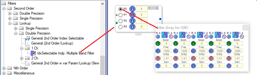
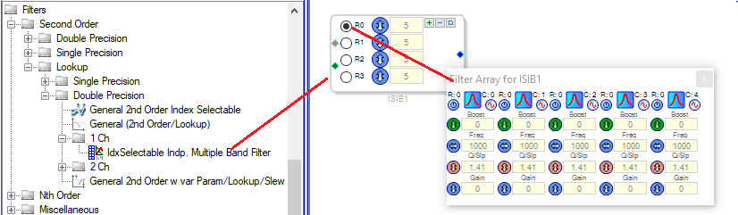
Yes, the ISFs generally work this way. However, there's no law against cascading several to build more complex filter sets. Also, have a look at this ISF -- it can expand to handle rather complex filtering:
Best regards,
Bob
Hi Bob,
Thank you! In my setting, I add an E2Prom to help restore the code to the -1701 chip so that every time the board reboots it will restore the code from E2Prom (or E2Prom will program the chip.. I'm still learning about the jargons). As for the ISF you suggest, I did not notice its existence, so thank you for your advice! I will look into that.
Thanks,
Joseph
Please log in to reply.