I2S in/out salve mode
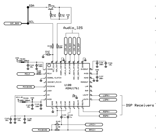
I’m trying to send and receive audio via I2S. AUDA1761 and CC2560 (BT chip from ti) are integrated into my circuit. In addition, I use two analog microphones and two analog speakers.
The microphones are connected to LINP, LINN and RINP, RINN and the speakers are tied to LOUTN, LOUTP and ROUTP, LOUTN pins.
Please see the below schematics:
BCLK (PCM Cloak Rate) = 2.112 MHz
LRCLK (PCM Frame Sync.) = 64 pr. frame (please see attached log file)
I have two following issues:
My device can be connected to a BT device and I get sound to the speaker, but the sound quality is very poor (almost noise).
There is no I2S output to the connected BT device, ie. no output from the DSP.
I can't see, what I'm doing wrong.
Br
Hossein
i2s
Hello Hossein,
I love your post because you gave us a lot of information. The only thing better would have been to zip up the project and attach it.
I see a lot that is wrong.
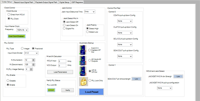
What is the frequency of your master clock coming into the part? You are using the fractional settings on the PLL and that is a little unusual.
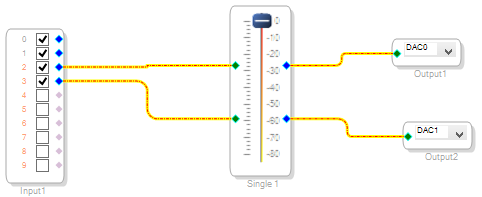
On your first screenshot your program is only taking input from the digital port. Inputs 0 and 1 are the ADC inputs which come from the mixers.
Then you are only going to the DACs. For now as a test I would use a "T" and also send the audio out of the digital ports. This is why you see no data is because you are not sending anything. The pull-down box for the output cell you can select the 8 digital channels.
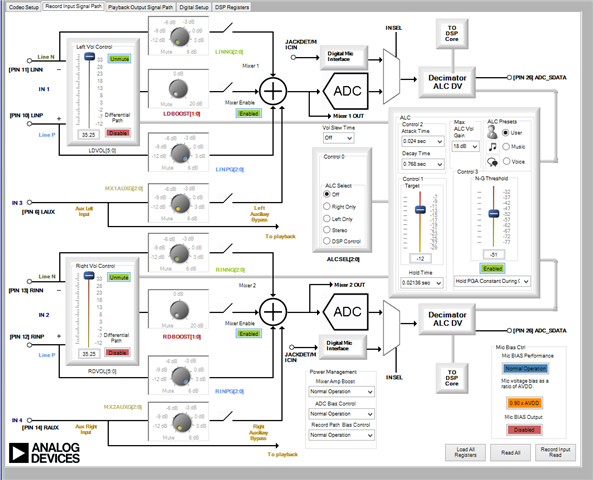
Then on the input mixer screen. You are only taking the "P" input from the mic and sending that out to the mixer. I would have to see how your microphone is connected but you will need to come into the differential input which is the center path. You do not have to use the extra boost but it will go through that signal path. So shut off the single ended "P" path and turn on the differential path. You do it with the enable button.
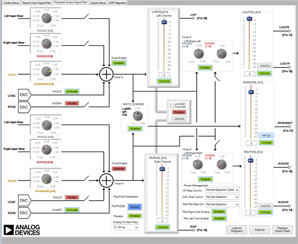
On the output side you are taking the DAC output and mixing it with the AUX input all in analog. I don't think this is what you want to do?
What is the frequency of the audio from the Bluetooth module? What is the format?
This will get you further along. I am sure there are things I missed.
Dave T
Hi Dave,
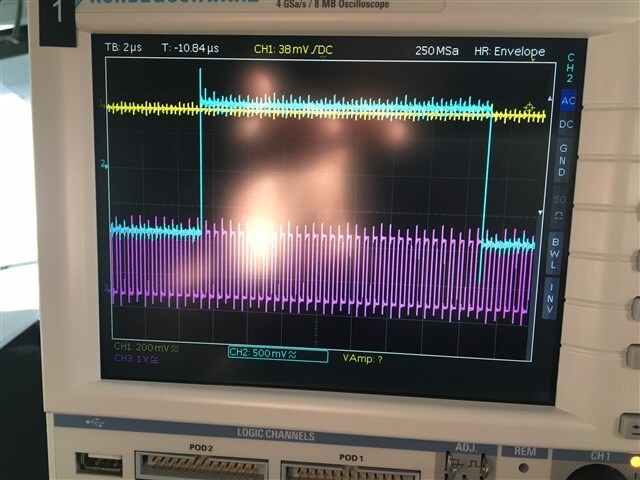
Thank you very much for your quick reply. Your advice has already helped a lot. now I have the output signal, please see below. But the sound from my device's loudspeakers is (very) unclear. I guess there is something wrong with the clock.
Please find below the zip file of the project.
Test_I2S.zip
Let me try to answer your questions.
1- What is the frequency of your master clock coming into the part? You are using the fractional settings on the PLL and that is a little unusual.
The frequency of my master clock is 24MHz. The reason why we use the fractional settings on the PLL is that, we just follow the AUAD1761 specification. Direct copy and paste from page 27 “Fractional Mode Fractional mode is used when the MCLK is a fractional (R + (N/M)) multiple of the PLL output. For example, if MCLK = 12 MHz and fS = 48 kHz, then PLL required output = 1024 × 48 kHz = 49.152 MHz R + (N/M) = 49.152 MHz/12 MHz = 4 + (12/125)”.
would you recommend using integer mode?
2- I would have to see how your microphone is connected.
3- What is the frequency of the audio from the Bluetooth module? What is the format?
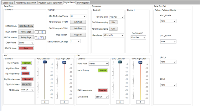
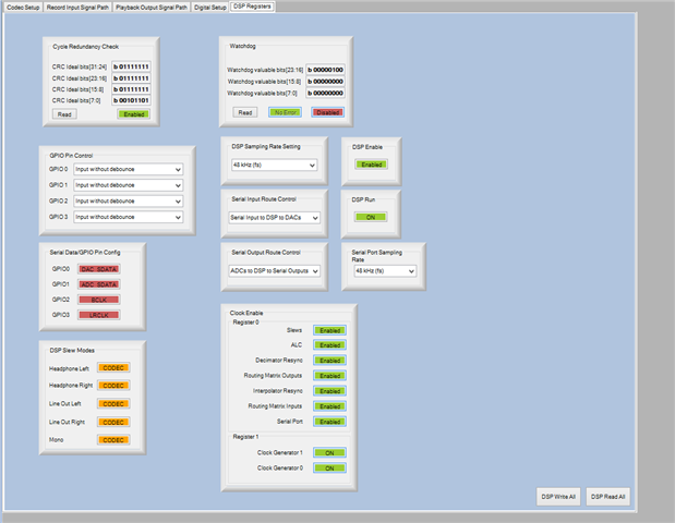
The format is I2S ( PCM 50% duty), the PCM Clock rate(BCLK) is 2.112M and the PCM frame rate(LRCLK) = 32k. please see below other settings for the serial port.
0x40, 0x08, // PCM clock rate = 2.112M (48kHz * 44clks)
0x00, // PCM clock direction 0x00 = master
0x00, 0x7D, 0x00, 0x00, // PCM frame sync = 32 kHz
0x00, 0x00, // PCM frame sync duty, (0x00, 0x00) = 50% of Fsync period (I2S Format), otherwise number of cycles of PCM clock
0x01, // PCM frame edge = falling edge
0x00, // PCM frame polarity = active high
0x00, // Reserved
0x10, 0x00, // PCM channel 1 out size = 16
0x01, 0x00, // PCM channel 1 out offset = 1
0x01, // PCM channel 1 out edge = falling
0x10, 0x00, // PCM channel 1 in size = 16
0x01, 0x00, // PCM channel 1 in offset = 1
0x01, // PCM channel 1 out edge = falling
0x00, //RESERVED
0x10, 0x00, // PCM channel 2 out size = 16
0x11, 0x00, // PCM channel 2 out offset = 17
0x01, // PCM channel 2 out edge = falling
0x10, 0x00, // PCM channel 2 in size = 16
0x11, 0x00, // PCM channel 2 in offset = 17
0x01, // PCM channel 2 out edge = falling
0x00, // Reserved
As I mentioned above, the sound out from our device speakers is unclear.
Thank you in advance
Hossein
Hello Hossein,
The file you attached was only the folder that SigmaStudio creates and deposits the compiler results into. The program is not in that folder.
From what you wrote and have shown there is a clocking issue. First, I am not sure if Bluetooth modules can be slaves on the I2S bus? I am not an expert on Bluetooth modules so I could be wrong.
First, I2S format will be 32 bit clocks per channel so that means 64 bit clocks per frame/sample period. So 32kHz fs will give you a bitclock rate of 2.048MHz. I have never seen a device that used 44 bit clocks. Plus, your statement of 32kHz fs and 2.112MHz bit clock does not divide evenly. It would be 15.151515... bit clocks per frame.
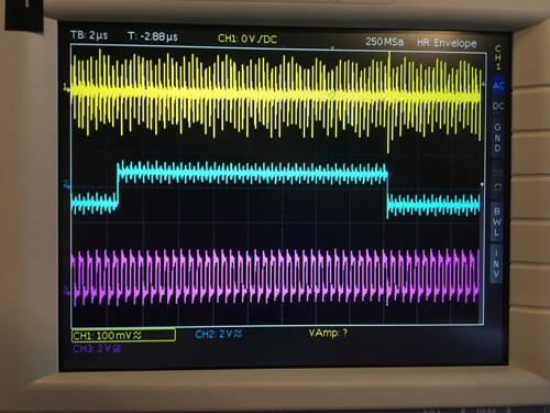
Your screenshot of the I2S looks kind of rough. Did you have the scope probes grounded? There is a lot of over and undershoot. Have a look at my post: https://ez.analog.com/audio/f/discussions/3510/how-to-take-meaningful-screenshots-of-i2s-audio-signals
Is your PCB only two layers? Do you have power and ground planes?
The reason why I questioned 24MHz is because it is also not a divisible frequency by 48kHz. For this processor it is not quite as important as long as you setup the PLL properly. But you may end up with more jitter than you like. So the best way to do this is to use a master clock that is either 256 x fs or 512 x fs. exactly.
I also see that you have a 220 ohm resistor on the MCLK input. That seems a little high to me. I would expect 22 ohms.
Dave T
Hi Dave
We got signals through our unit, in both directions(In/out). We had a couple of issues with clocking. Thank you for your good advice.
Is your PCB only two layers? Do you have power and ground planes?
Our PCB is 4 layers and thee are both power and ground planes.
Next time we build HW, we will change the 220 ohm resistance on the MCLK input with resistance 22 ohm.
Thanks again, Dave.
Please log in to reply.