SigmaStudio 4.5 with ADAU1761
Hi -
I need some guidance on getting SigmaStudio 4.5 DSP core functionality working on my ADAU1761.
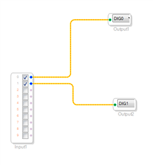
I have a custom designed USB analog microphone board with a BF706 and ADAU1761. I've successfully programmed all registers in the ADAU1761 manually via the BF706. The mic and design work very well and as expected. I have also successfully used SigmaStudio 4.5 to generate and load an image into the ADAU1761 via BF706 with the same registers I manually programmed using Analog Devices provided code adi_adau1761_SigmaStudioLoad() in adi_adau1761.c. The problem arises when I simply change the Serial Output Route Control register in SigmaStudio from "ADCs to Serial Outs" to "ADCs to DSP to Serial Outs", enable DSP, set DSP run ON, and add simple ADC L/R input to Dig0/1 serial outputs schematic routing as shown below. The serial output data is trash (periodic large scale value swings).
Questions:
1. See attached SigmaStudio 4.5 project files. What am I doing wrong that prevents the SigmaStudio image with DSP core enabled from working on ADAU1761 as expected? Are there additional registers that need to be set to use the DSP core?
2. I believe SigmaStudio 4.5 does not correctly generate ADC Control 0 register output. The "Dig Mic In Select" GUI box is backwards. In other words, for ADC use, "Mic In" needs to be selected in order for INSEL bit in register 0x4019 to be a 0 (0 = digital microphone inputs off, ADCs enabled).
Thanks in advance!
Dave
SigmaStudio proj.zip
Audio Signal Processors
sigmastudio
SigmaDSP Audio Processors
adau1761 how use dsp
adau1761
Hello Dave,
What is the master clock frequency?
Is the serial ports a master or slave?
If they are a slave then is the source using the same master clock?
I will look at the project now.
Dave T
MCLK is 24MHz. Master serial ports
Thanks David,
Is it exactly 24MHz or 24,576MHz?
Dave T
Exactly 24MHz. I set up the internal PLL in fractional mode to obtain 48kHz sample rate.
Hello Dave,
Yes, that all looks good in your project.
First, I should mention that the register for the MIC verses the ADC is just setup in a horrible way. I can say that because it was done before I was here. The text in the field is "MIC IN OFF" and "ADC IN OFF". That alone is confusing but to make things worse when you deal with Windows and how it scales text size based on user settings and monitor resolution I often see some of the text cutoff. So you cut off the text and all you see is "MIC" and you do not see the "OFF" making it look like it is backwards. I certainly would have changed the labels on the buttons but there is no changing it now.
For the other issue. I am not seeing anything popping out at me as to why you are seeing this. I do notice that the signal going to the headphone or line outputs is not just the DAC but it is the DAC with the analog feed forward of the mic signal on the input side. So if you are taking the serial output and turning it around to the serial input to go to the DACs then this might be part of the issue. But this would just cause phase issues etc., not loud spikes in level.
So it was OK when the ADCs are going directly out of the serial port?
One other thing to try is to setup an oscillator in the DSP and send that out of the serial port. This will simplify some things. You can also send the ADC to the DACs as an experiment.
Dave T
Hi @DaveThib
I have some additional info for you on this problem, but still looking for more recommendations to help solve.
First, to answer your questions.
1. The application is a USB microphone. So, the audio chain is as follows:
Stereo Mic analog inputs > ADAU1761 ADCs > ADAU1761 DSP > ADAU1761 Serial Port out > BF706 > USB
USB > BF706 > ADAU1761 Serial Port in > ADAU1761 DACs > Stereo Headphone outputs
As you noted, I have the mic and DAC signals mixed to the headphone outputs. This is by design to allow a user to simultaneously hear the mic as well as playback from USB. As mentioned, our device is fully functional and working well without using the ADAU1761 DSP core. As soon as DSP core functions are added using SigmaStudio 4.5, garbage comes out of the serial ports. I did try to remove the mic signals from headphone mixers with no noted change in performance.
2. Yes, when SigmaStudio 4.5 is used to load ADAU1761 registers and simply route the ADCs to serial port output, it works OK.
3. Simply placing a 1kHz oscillator to the L serial output results in not hearing anything from that channel. I've tried ticking/unticking the oscillator on/off box.
NEW FINDINGS:
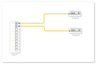
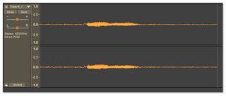
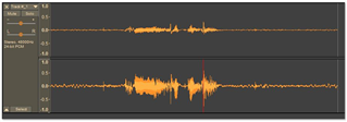
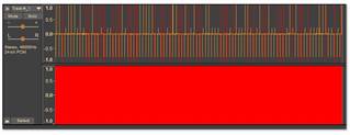
A. Routing ADCs to serial ports works (with DSP core enabled):
(L and R channels shown in Audacity upon speaking into mic)
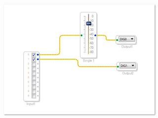
B. Placing a volume control prior to serial output works:
(L and R channels shown in Audacity upon speaking into mic)
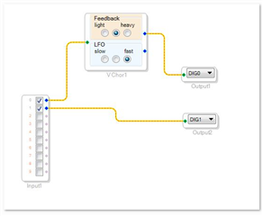
C. Placing a chorus on L channel prior to serial output does not work:
(L and R channels shown in Audacity with garbage)
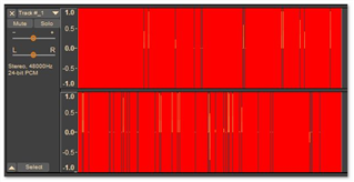
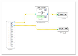
D. Placing a pitch shift on L channel prior to serial output does not work:
(L and R channels shown in Audacity with garbage)
Question:
1. Are there other registers that need to be set up when more complex DSP functions are used?
I'll read back the ADAU1761 program memories to make sure they match the SigmaStudio output file.
Thanks
Hi DaveThib
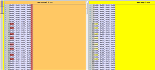
I performed a Program Memory dump from ADAU1761 and it 100% matches the Program_Data_IC_1[PROGRAM_SIZE_IC_1] array. Program Memory residing after byte number
PROGRAM_SIZE_IC_1 is garbage, but I'm assuming that the program never reaches those instructions due to the documented jump command.
I also performed a Parameter Memory dump. With the exception of the below differences, it 100% matches. I'm assuming the differences are the four 0 bits added before the MSB to extend the 28-bit word to a full 4-byte width?
Do you have any additional ideas for me to try in order to get the DSP core working?
Thanks.
Hello David A,
I am not sure what is happening here. I think you may have a corrupted project file so starting over from a blank project might be a good idea. Or the clocks on the PCB may not be running at the correct frequency. Since you have the serial ports setup as a master coming out of the 1761, you can simply connect a scope to the LRCLK output and see if it is indeed running at 48kHz. If there is something wrong with the clock s or the settings it would not be correct.
I quickly slapped together a project with both the vocal chorus and the pitch transposer and they both work fine with Rev 4.5. I have attached the project here. Just be careful to not select the serial port input because it will setup a feedback loop. I have the serial data output jumpered back to the serial data input so it is a risk for me.
You can zip up your project and attach it to your reply and I can see if it works over here.
Thanks,
Dave T
ADAU1761 Test of Vocal Chorus and Pitch Trans.zip
Hi DaveThib
Thanks for the reply. LRCLK is right at 48kHz and BCLK is right at 3.072MHz. Serial Data Out is periodic toggles representing the same garbage data I describe above.
I've unsuccessfully tried to compile and load your project on my hardware. Attached is my Sigma project and supporting compiled files. Any help or suggestion on what to try next is appreciated.
Also, what version of SigmaStudio are you using?
Dave2211.ADAU1761 Test of Vocal Chorus and Pitch Trans.zip
Hello David,
I had some time today, or should I say I took some time today, to look into this some more. I opened and used your project on an eval board. I had to change the PLL to be integer for a 12.228MHz MCLK. Then I also changed the input to the ADC to be using the single ended Aux inputs and the output of the DAC to use the line outputs.
The project worked fine.
Then I connected the serial interface of the Audio Precision to also bring in a digital signal and read a digital signal. They worked fine. So I really do not know what could be the issue. Your project is right at 50% MIPS usage so if there is an issue with the PLL not putting out the correct frequency then it might be good to try a smaller program.
I am using Rev 4.5 of SigmaStudio.
So I think we need to narrow this down to just the serial port? Do you also hear the issue with the DAC output?
Try just feeding the serial port with an oscillator in the DSP so the ADC and serial input port is not in the equation?
Have you checked the clocks coming out of the serial port that they are indeed the correct frequency? Because this would verify that the PLL is producing the correct system clock.
Dave T
Hi DaveThib
Thanks again for looking at this issue with the ADAU1761 used in a USB microphone application with BF706. I'm still having problems.
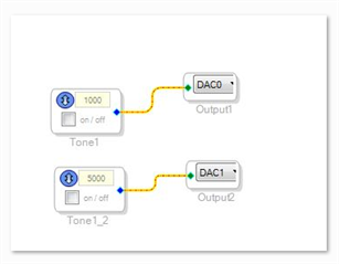
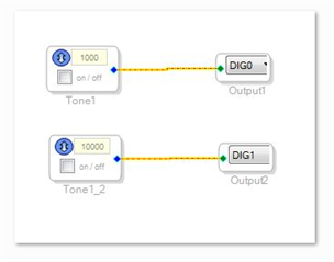
I've created two SigmaStudio images that simply generate sine waves to 1) the DAC outputs feeding headphones/line out and 2) the serial outputs - see schematics below. Both do not work as expected. I'm hearing what is best described as a machine running (see attached MP3 recorded from Audacity).
To summarize the development to date...
- I've successfully programmed all registers in the ADAU1761 manually via the BF706. The mic and design work perfectly well and as expected. I have also successfully used SigmaStudio 4.5 to generate and load an image into the ADAU1761 via BF706 with the same register values I manually programmed using Analog Devices provided code adi_adau1761_SigmaStudioLoad() in adi_adau1761.c. That works well too. The issue I am still having is when I create a SigmaStudio image that inserts any kind of DSP functionality.
- All ADAU1761 IC voltages have been verified
- All memory has been read back and verified against SigmaStudio config image
- ADAU1761 uses input MCLK of 24.00MHz in master mode. LRCLK has been measured at exactly 48.000kHz. BCLK has been measured at exactly 3.07200MHz. These frequencies should be correct for 48kHz samples and 32 bits/channel or 64 bits/frame.
- Within SigmaStudio, I've created an image which does not use the PLL as opposed to fractional PLL. Does not work.
- Within SigmaStudio, I've created an image which uses integer PLL as opposed to fractional PLL. Does not work.
QUESTIONS:
A. Since you are able to run my projects on your board (presumably via USB download from SigmaStudio IDE), I'm wondering if there is anything special I need to do when loading the SigmaStudio image from the BF706 when using SigmaStudio DSP functionality. Recall, I can successfully generate and load a SigmaStudio image into the ADAU1761 via BF706 with the same register values I manually programmed using Analog Devices provided code adi_adau1761_SigmaStudioLoad() in adi_adau1761.c. At the moment, I'm simply calling that function in my code after driver setup. I've also tried the steps outlined in the STARTUP section on Page 45 of the Rev E datasheet.
B. Are there any other ADAU1761 registers settings required to be changed (other than Serial Input/Output Routing Control) when using SigmaStudio DSP functionality?
C. Any other diagnostic steps I can try?
1) SigmaStudio DSP image schematic of sine wave oscillators routed to DAC outputs (note the "on/off" box was tried checked and unchecked with no difference).
2) SigmaStudio DSP image schematic of sine wave oscillators routed to Serial Port outputs (note the "on/off" box was tried checked and unchecked with no difference).
Sound wave recording of "machine noise" obtained by using image 2) above.
Play this audio clip
Hi DaveThib
I still cannot successfully utilize any DSP functions from SigmaStudio 4.5 on my ADAU1761 exported then loaded from a BF706. This problem is now critical in our schedule; so I really need your help in solving.
Recall that I am successfully able to utilize SigmaStudio to set the registers and schematic for a simple mic to I2S and I2S to DAC. The problem occurs when I utilize any DSP core function. I either get garbage or nothing at all out of the ADAU1761.
I've tried a 2nd board - same results.
I've tried SigmaStudio 4.5 Beta - same results.
I've read back Parameter RAM and Program RAM and verified against exported file contents.
Thinking about the differences in files exported from SigmaStudio between what works for my ADAU1761 and what does not work, I'm wondering if the problem is with Non-modulo RAM or Safeload.
Questions:
1. Safeload. I've read the several forum threads about Safeload, but it is still not clear to me. If the BF706 calls default_download_IC_1() from within adi_adau1761_SigmaStudioLoad() at power up, is there anything else I need to do with Safeload per page 47-48 in the datasheet? Or does Safeload happen automatically within the ADAU1761?
2. Loading non-modulo memory. Anything special that needs to be done or is it just a matter of running the default_download_IC_1() function?
3. Is there a new version of adi_adau1761.c with associated loading functions?
4. Any application notes on loading an exported SigmaStudio image to ADAU1761 via BF70x?
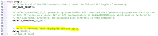
5. In the SigmaStudio wiki, it has teensy_sigmadsp_example_project_1.1.0.zip as a reference for loading exported SigmaStudio code. In main.cpp, why is the image loaded twice separated by a 10 second delay?
Thanks again...
Hi DaveThib I haven't seen any updates on this thread with answers to my above questions. I'm still in need of help. Is there a way you and I can talk on the phone in order to brainstorm and expedite? Thanks!
I solved the problem by using a corrected TWI_Write() function located in adi_adau1761.c from ADI_ADSP-BF706_EZ-KIT_Mini-Rel1.1.0.exe. It also increased the amount of memory used for adi_adau1761_Open() by adding PROGRAM_SIZE_IC_1.
This is my memory allocation now:
static unsigned char m_user_adau1761_codec_mem[ADI_ADAU1761_MEMORY_SIZE + PROGRAM_SIZE_IC_1];
I'm finally able to engage the DSP core features and obtain nice output from the CODEC!
Please log in to reply.