PDM microphone clock frequency settings and left, right channels data
Hi Team,
Two more questions on this subject.
1) PDM microphones that are connecting to the J2 LRCLK_IN2 and J2 BCLK_IN2 pins on the EVAL-ADAU1452 board. The PDM microphones have 2.4 MHz typical frequency. How do I configure the BCLK_IN2 to operate in 2.4 MHz?
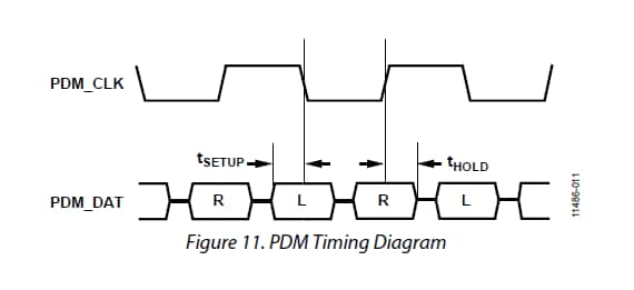
2) Does the LOW level clock time period clock in the Left (DMIC_CTRL0) PDM data channel by default?
3) Does the HIGHT level clock time period clock in the Right (DMIC_CTRL0) PDM data channel by default?
regards,
ping
Audio Signal Processors
adau1452
pdm microphone
adau1452 sigmastudio
SigmaDSP Audio Processors
Hello Ping,
The left/right relationship is shown in the specifications section of the datasheet.
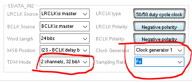
To configure the bit clock frequency, simply setup the serial port to produce the desired frequency but using all the serial port settings.
Three of the registers will affect the bitclock frequency:
The TDM Mode that selects how many channels and how large the channel slot is is one of them.
The Clock generator to use is another selection,
Finally, which tap off of the clock generator is to be used.
If you select a stereo, 32 bit channel slot and a clock generator that is setup for 48kHz and you select the 48kHz tap off of the clock generator, then this is how you would calculate the bit clock frequency:
fs x slot size x number of channels.
So 48K x 32 x 2 = 3,072,000 Hz
If you select the fs/2 tap off of the clock generator, then you would get:
24k x 32 x 2 = 1,536,000 Hz.
So manipulate all the clock settings and the serial ports to create the bit clock frequency you need.
Dave T
Hi Dave,
Very thanks for your detailed answer.
I have tried to use Clock Generator 3 with N=42 and M=320 to generate a 37,800 Hz fs and therefore BCLK will be 37,800 x 32 x 2 = 2,419,200 Hz. This value is closer to STM MP23DB01HP PDM Digital Microphone typically running with 2.4 MHz.
But the voice output comes with too much noise. Are my N and M values good for generating appropriate 2.4 MHz BCLK?
Regards,
ping
Ping,
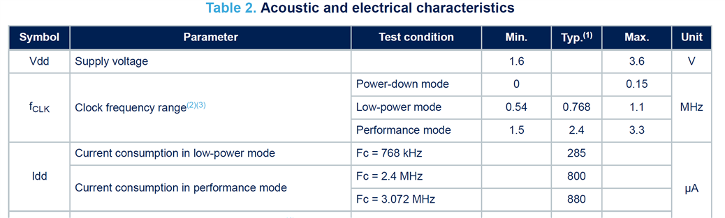
Is there a specific reason that you would like to run this mic at 2.4 MHz clock rate? According to the datasheet, that part can run at a broad frequency range up to 3.3 MHz. I would strongly recommend that you give the PDM mic a clock frequency of 3.072 MHz, which is 48,000 * 32 * 2. Running at the slower rate of 2.4 MHz will only reduce the bandwidth.
One reason that you are getting a lot of noise is jitter. The ratio of 32/420 will give an average clock frequency of approximately 2.4 MHz. However, the accuracy of the period of this clock is limited to the resolution of MCLK, which is 12.288 MHz. The duty cycle of the clock will be quantized to the MCLK rate. Therefore, some periods will be slightly longer and some slightly shorter to give an average rate of 2.4 MHz, and that produces jitter which manifests as noise. By using a simple integer ratio like 1/6, this noise will not appear.
Unless you absolutely need to run the mic at 2.4 MHz, running it at 3.072 will produce better results: more bandwidth, less jitter, and no need to use an ASRC to get back to the core rate.
Ken
Please log in to reply.