ADAU1701 music level output to LEDs
Hello,
I would like to build an optical level meter.
For this implementation I need a clean solution to get a signal from the DSP.
As usual for a power amplifier I want to build a LED matrix, which shows the current db-level from -96 db to 0 db.
The LEDs are controlled by an Arduino, which only needs a signal from the DSP about the current db level.
Two options came to my mind:
- a GPIO is used as output, where a PWM signal is modulated (0% for -96 db and 100% for 0 db)
- the current db value is sent via I2C to a slave.
Are there any other variants?
Could someone build me the blocks together, because I haven't found a way to implement the whole thing in SigmaStudio yet.
That would make me very happy.
Joe
Audio Signal Processors
Audio Products
software
i2c
SigmaDSP Audio Processors
pwm
adau1701
Show More
Hello Joe,
I did something similar but with a Sigma300 part so you would not be able to do this with an ADAU1701. I will put in the link for others who might be interested.
(+) Could anyone explain Voltage Controlled Pulse problem on Duty control? - Q&A - SigmaDSP Processors & SigmaStudio Dev. Tool - EngineerZone (analog.com)
It seems to me that trying to modulate a GPIO to "tell" an Arduino the level the audio is making this more complicated than it should be.
I assume you have the I2C port of the Arduino connected to the DSP? Then you can just pole the DSP for the level. There are many ways to do that and they are mostly fairly simple.
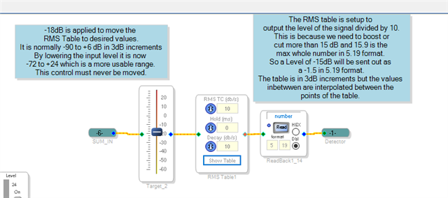
I think the easiest way would be to use an RMS table to decode the level and you can read the output of the RMS table.
Here is a post with a link to an example project for an AGC. In this project I am using an RMS table to sense the level. You can use this to have the Arduino read the readback value and multiply it by 10 to get the result in dB. Today is kind of a hectic day for me so I cannot build up the exact project but this will give you an idea of how to do it. This is the section of that project:
Here is the post talking about it
(+) Automatic gain control using ADAU1701 - Q&A - SigmaDSP Processors & SigmaStudio Dev. Tool - EngineerZone (analog.com)
Dave T
Hello Joe,
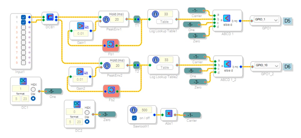
The RMS table which David employed can also work on the ADAU1701. My version below drives the lookup table with a Peak Envelope Detector. The feedback around this block produces a dB-linear decay characteristic -- when the audio ceases, your LED bar slides evenly towards -90 dB instead of hanging near 0 dB then dropping quickly. Adjust Gains 1 and 2 to vary the decay rate. Finally, the two ABCD Comparators work with a waveform oscillating between 0 and 1.0 to generate the PWM signals. In my testing the circuit lights up two LEDs on my evaluation board; it appears to work fine.
I'm afraid I'm not very savvy with the I2C method, yet it may save some instructions should this be necessary.
PWM-1701-Log-Lvl.dspproj
Best regards,
Bob
Please log in to reply.