ADAU1701 I2S output to PCM5102 DAC
Hello!
I've been working on creating a 5-channel speaker system with the Dayton Audio KABD-430 (which uses the ADAU1701 chip) for some time now, and I've been having a lot of trouble with the 5th channel.
Basically, I'm trying to convert the I2S output of the KABD-430/ADAU1701 into an analog signal to be used on a separate amp by using a PCM5102 chip (https://www.amazon.com/dp/B07Q9K5MT8) to act as a 5th channel.
Whenever I have everything hooked up properly though, I get a low hiss from the output of the PCM5102. I've triple-checked everything I know to check, but I still can't get an output. Below are screenshots of my SigmaStudio config.
Thank y'all for any help y'all can provide.
Audio Signal Processors
Audio Products
hardware
i2s output
i2s
SigmaDSP Audio Processors
adau1701
dac
unknown
Show More
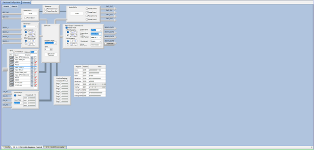
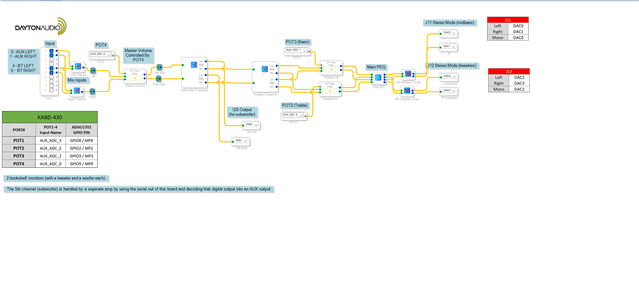
Hello ChasePratt,
I am going to guess that you need to supply the DAC with a master clock from the 1701 board. There is not really enough information on the Amazon page to answer the question but I see pins for LCK, DIN, BCLK, SCK.
So that would be LRCLK which is the sampling rate clock
BCLK would be the bit clock for clocking in each data bit.
DIN is the data.
So that leaves SCK. I have no idea what it is expecting for that signal? The ADAU1701 board I am pretty sure is using a 256x fs crystal for the master clock. The problem is that you cannot just tap off of that to send it to another board. The extra capacitance will cause issues with the crystal and it might have issues starting up.
I would find out what the expected clock signal is and then figure out a way to supply it. I will try to help with that.
Dave T
Thank you for the help - I believe the DAC is designed to work with a Raspberry Pi, but the reviews of the DAC on the Amazon page specifically say to bridge the ground with SCK to force the DAC to generate its own clock signal. I have essentially no knowledge of circuit design, but I'd venture a guess that the SCK the DAC automatically generates does not match the clock that the ADAU1701 has.
Hello ChacePratt,
Have you taken a scope and looked at the signals to verify the correct clock signals are on the correct pins?
Also to verify that the data is correct?
I wrote this post on how to take screenshots of I2S signals and it is helpful to learn how to setup the scope to do this.
(+) How to Take Meaningful Screenshots of I2S Audio Signals - Q&A - Audio - EngineerZone (analog.com)
This might give us some clues on what might be the issue here.
What does the PCM5102 datasheet say about the master clock? Or I guess the serial clock? What is strange is that usually the term serial clock is for the clock that clicks in each bit and we call it bit clock. So I am not really sure what this pin is expecting.
I do not have time to study the 5102 datasheet right now even though it is good to know the competition's parts...
Dave T
I appreciate your guidance and help, but unfortunately, I do not own a scope. Is there any other way to verify that things are working how they should? I have a multimeter, but I can't imagine that's going to help a whole lot.
Anyways, the PCM5102 datasheet provides some information that verifies the claims of people on the Amazon reviews for the DAC I bought:
"The system clock PLL mode allows designers to use a simple 3-wire I 2S audio source when driving the DAC. The 3-wire source reduces the need for a high frequency SCK, making PCB layout easier, and reduces high frequency electromagnetic interference. The device starts up expecting an external SCK input, but if BCK and LRCK start correctly while SCK remains at ground level for 16 successive LRCK periods, then the internal PLL starts, automatically generating an internal SCK from the BCK reference. The PCM510x disables the internal PLL when an external SCK is supplied; specific BCK rates are required to generate an appropriate master clock. Table 5 describes the minimum and maximum BCK per LRCK for the integrated PLL to automatically generate an internal SCK." - This was on page 12 of the datasheet.
Basically, the SCK shouldn't have to be used and just needs to be grounded (which I've already done), but it still fails to work.
Page 11 has some info that might be able to help with the SCK input. SCK is described as the "system clock input."
Hello Chase,
Without a scope to verify signals you are in essence trying to figure out what is not setup correctly, with the correct colors, in a room while wearing a blindfold.
You can get a decent one now for around $300-$400!
So right now you cannot tell if you are providing the correct signals on the correct pins so you have no idea if the problem is with the DSP or the DAC or the interconnections.
Dave T
Gotcha. Thank you for the help and info - I will look into buying a scope in the future.
Please log in to reply.