ADAU1452 register configuration and output audio distortion issues
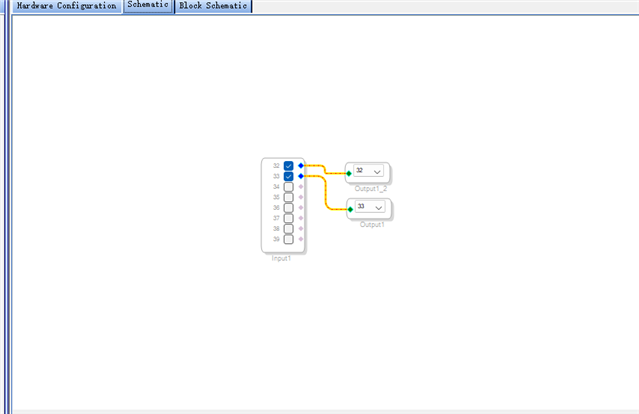
See the following picture for the specific configuration.
This is the pass-through program I configured in sigmatudio4.7. Audio is through this pass-through program after the AP collection and check that its THD+N will bounce back and forth.
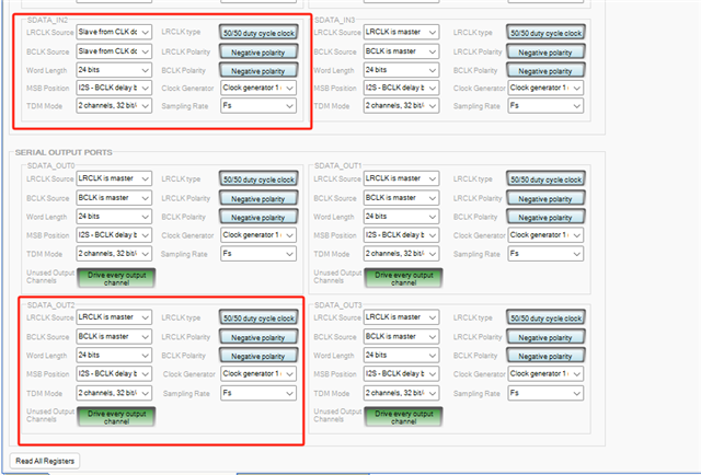
I only configured this in sigmastudio4.7, along with some of its input and output registers, see the following figure:
Here I only used the input and output of serial port 2, and the rest of the input and output were ignored.
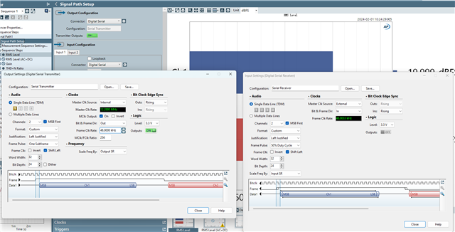
The following is the configuration picture in AP. I don't know whether I have problems in each configuration, so I upload the pictures.
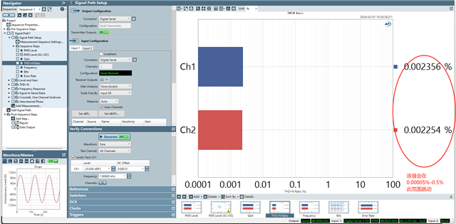
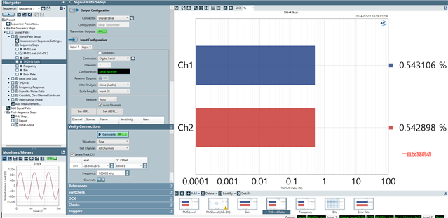
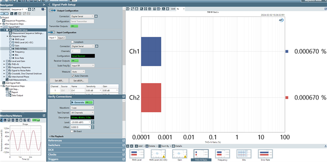
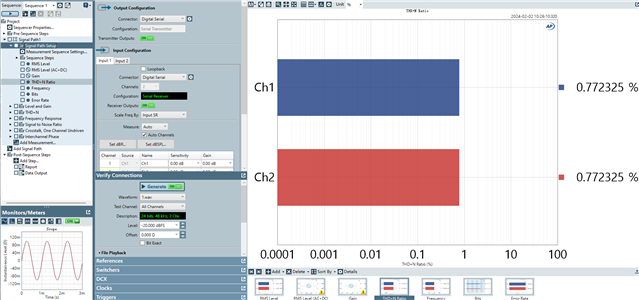
The following two pictures are THD+N pictures collected by AP after the audio passes the above procedure:
Both before and after are audio messages collected from ADAU1452, where they are bouncing in a certain return.
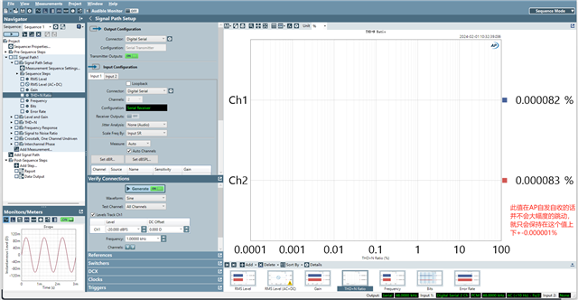
The following figure is the AP sending the same audio, but it does not go through the ADAU1452 to collect the audio THD+N message, this will not bounce back and forth, maintain at 0.000082%. Obviously this should be a problem with my configuration in ADAU1452, so I would like to ask what can be done to solve this problem?
I look forward to your reply and thank you very much.
Thanks
Weiqi
Audio Signal Processors
adau1452
Audio Products
software
but the THD+N Ratio of the audio received back by AP after the audio is input will always circulate and float.
SigmaDSP Audio Processors
I have configured a pass-through program in the ADAU1452DSP
Show More
Hello Weiqi,
This is an issue with the Audio Precision where it cannot function with two different clock rates. you have one as a master and one as a slave so the AP is only locking to one of these and the other is drifting in and out. We had updated our APx software that I think fixes that, I am still using an AP-2700 at my station and it absolutely cannot lock to two different clocks.
So I suggest you change your setup so you only use one set of clocks. Make the AP master for serial in and out or make the DSP master for serial in and out and that should fix it. The only problem with this is that when the direction of the clocks is opposite of the data, then the timing margins suffer. If you try to run at a faster sampling rate you will start getting errors.
You should also let me know what hardware you are using? Is it one of our evaluation boards or your own hardware?
I also want to mention you are doing well to start simple and get the communications up and running first!
By the way, if you have further questions about the ADAU1452 you can post them in this space in the forum:
(+) SigmaDSP Processors & SigmaStudio Dev. Tool - EngineerZone (analog.com)
This is where you will find many answers and I manage that forum space.
Thanks,
Dave T
Hello Dave
I am very glad to receive your reply.Perhaps due to the time difference, I could not immediately test the solution you gave when I received your reply.
Let me first explain my side of the hardware circuit, I use our own hardware device, but in the hardware principle, I just pull out the I2S input(BCLK2_IN、LRCLK2_IN、SDATA2_IN) and output(BCLK2_OUT、LRCLK2_OUT、SDATA2_OUT) pins.
In addition, our audio measurement equipment uses APx555 and software uses AP500x 8.0
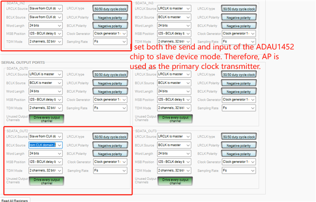
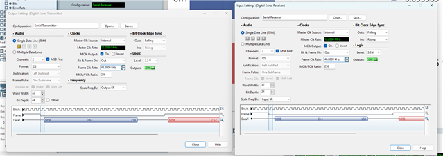
I have now set AP as the primary device. He acts as the maindevice in both serial input and serial output to send CLK please take a look at the following configuration.
The following is the configuration of the APx500:
After completing these configurations, I observed that the given THD+N image seemed to fluctuate as before.
So I'm wondering if this is related to other issues, such as other configurations in ADAU1452?
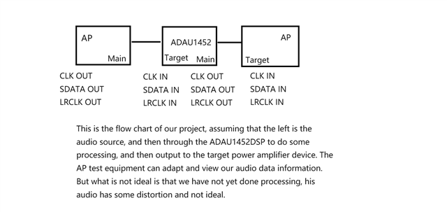
The following is the process of our project, hoping to make you understand my doubts better.
Thanks,
Weiqi
Hello Dave,
Additional information: Thank you very much for your reminding, I will ask other questions in the future in the community you recommend
Thanks,
Weiqi
Hello Weiqi,
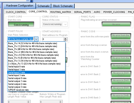
Great, now that you have the Audio Precision all synchronized, now you need to have the DSP core run the program synchronized with the clocks from the AP.
You can use ether the Serial input or output ports to do this since they both have the same clock on their pins.
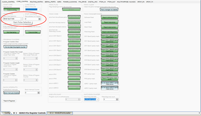
The DSP Start pulse register is where you select the clock that sets the actual sampling rate. You need for it to follow the rate from the AP.
That should do it.
Yes, the time zone difference is always a problem. I deal with it daily.
Dave T
Hello Dave,
Thank you very much for your help.I'm sorry I gave you trouble on the weekend.
After I adjusted it with your help, THD+N did not fluctuate up or down.
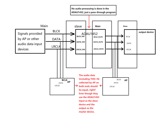
But I have a new question, that is, why can it collect signals correctly when its input and output ports are used as slave devices (when the AP clock is in charge)? Is this an AP problem? Because you look at the schematic below, if we don't make some changes to the audio data in the ADAU1452 chip. According to the knowledge theory, by comparing various BCLK, LRCLK, etc., we should also be able to collect THD+N from AP that is consistent with the input end, right?
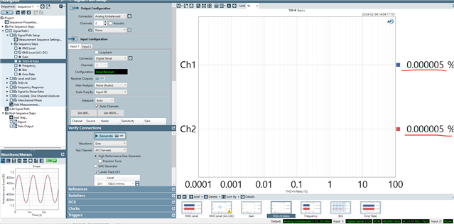
But the reality is not so, the ADAU1452 left input received a stable 0.000005% (THD+N).
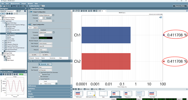
The output port on the right side of the ADAU1452 is measured in 0.4% to 0.5% floating data. I know that setting the input and output to slave mode and then changing the configuration you give should solve the problem, but our project here is to let the output of the ADAU1452 master.
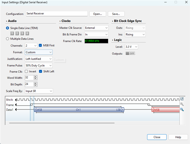
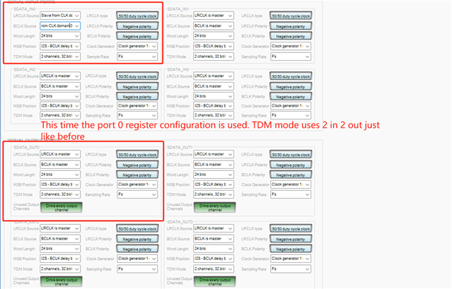
Here are my Settings for receiving the AP on both ends (ADAU1452 input and output)
The following is the Sigmastudio configuration:
During this period of time, I also did some thinking, I failed to capture the effect I wanted at both ends of the ADAU1452, perhaps because the register Settings of the ADAU1452DSP were not properly set in Sigmastudio, or the register configuration of the ADAU1452 was not consistent with the configuration of the AP. This may enable the same audio data to be collected from the device without both the input and output.
Thank you again for your reply to my doubts. I hope to receive your reply again. During this period, I will also study together.
Thanks,
Weiqi
Hello Weiqi,
In your block diagram you did not include where the master clock is coming from and what parts are using it?
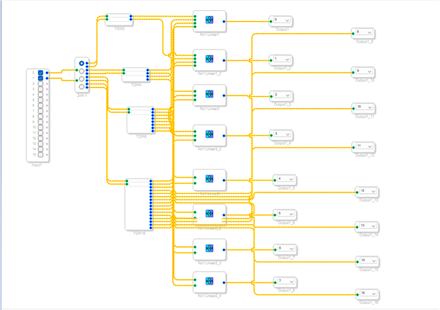
Your diagram and screenshots do not agree with what you have been telling me. You are going out of the AP with an analog signal not a digital signal. So where are the ADCs and how are they clocked? Then in your project, what caught my eye are hierarchy boards labeled TDM2, TDM4,TDM8 etc. You only have the same stereo two channels of audio going into these blocks. This is not now you would change to different TDM modes. This all happens in the serial port configuration not in the DSP core.
Can you provide your SigmaStudio project and your Audio Precision project?
If you can get me these three things it would help, the master clock included in the diagram, the signal flow that includes the ADC in the diagrams and then your projects.
Dave T
Hello Dave,
Yeah, I'm sorry it's different.The purpose of our project is to change the register in ADAU1452 through I2C to make its TDM mode change. TDM2, TDM4, TDM8 and TDM16 that you see are all after changing the register, because with the change of TDM mode, its channel will also change. So I'm using this selector over here to select which channel it needs to go through.
I know what you said, so I used the I2C bus in the MCU to manipulate the DSP registers to make changes, and also to change the number of channels opened.
In addition, I do not quite understand your statement that the data sent by the AP is analog data rather than data audio data. Could you please elaborate on that?
Hello Weiqi,
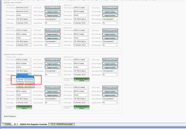
This is from your screenshot:
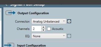
You are using the analog output of the Audio Precision not the digital serial output.
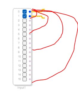
Yes you need to change the registers to the correct TDM mode. However, the serial port will place the channel data into consecutive memory locations for the core to pick up. The serial input port GUI has the inputs shown.
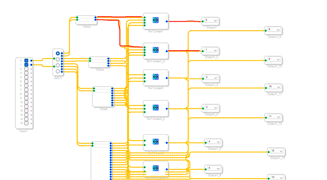
I took this screenshot and scribbled red lines to show where the TDM2, TDM4, TDM8 and TDM16 signals will appear.
I did not show the lines perfect but TDM4 is inputs 0-3. TDM8 is inputs 0-7 etc.
You will need to change some of your routing but the way your project is structured you are only picking up the first two channels of any of the TDM formats.
Dave T
Hello Dave,
Ok, I think I know what you mean. But maybe you misunderstood me a little because I didn't make it clear before. Please allow me to explain to you the screenshot of AP and what I want to do with ADAU1452.
The first is the AP screenshot, now my AP measuring instrument is only to do a revenue end, do not do the sending end, my audio signal is sent from other places, and then received from the input end of the AP, yes, now the AP sending end configuration do not look.
Secondly, what we want to do in ADAU1452 is to input two I2S and output TDM2, TDM4,TDM8 and TDM16 modes. This means that our input TDM mode does not change, and the output needs to change. Therefore, only two channels Ch1 and Ch2 signal will appear.
The problem I am facing now is that I have not changed the format of the ADAU1452 input and output TDM so that it defaults to TDM2. Then the ADAU1452 input side, and output side I only use AP measurement, now in my hardware, I do not let AP as the sending side. So if I didn't do any audio data processing in the ADAU1452, then the audio data I captured using AP at the input and output should be the same, right?
However, if you look at the image of the input and output captured by the AP below, it is obvious that their THD+N is not the same.
Input:
Output:
The configuration of the AP mentioned earlier refers to the configuration where I use the AP to capture audio data. At this time, the AP only has the function of capture, I am not using the AP to send audio data, the audio data at this moment is the digital signal that I send from other places.
I hope this time I can explain my confusion.
Thanks,
Weiqi
Please log in to reply.