adau1401 miniDSP wont properly boot analog signal inputs upon start, need help
Hello there,
First of all im apologising if my question is too trivial or misplaced into wrong place of this wonderfull web-page, which im newby at.
Long story short, iv got myself a ADAU1401 minDSP development board ( the green one from aliexpress/ebay etc) + Cypruss EZ-USB USBi emulator ( which is working correctly after some finicking around it),
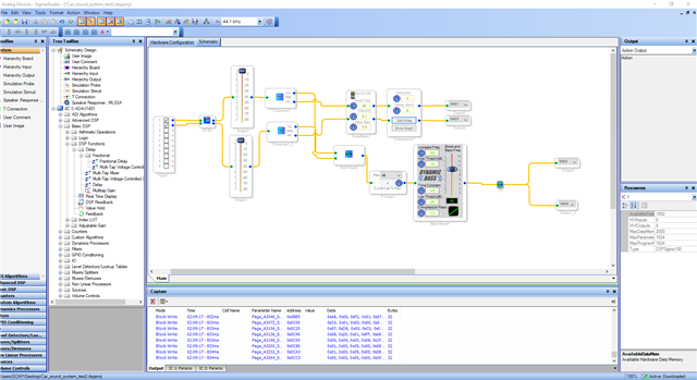
and my main problem at the moment is driving me crazy - i have small schematic for such setup:
2x analog inputs from audio source ( L/R channels ), which im futher crossing over for car subwoofer and stock speakers, at the end in schematic i have 2x L/R HPF crossowered channels with additional +1 mono LPF and Dynamic Bass-Boosted channel.
When i compile/download the schematic, it works wonderfully, and i really like how it sounds at this testing phase before i change my bmw e39 stock stereo system.
I can also write the programm to ic_1, and then check against recent compile / eeprom and it passes, but once i power-cycle adau board, sound from analog inputs doesnt pass to outputs. However
if i then re-check the compiled file vs eeprom contects, it passes as success, leaning me to think that maybe only DAC part or analog inputs did not initialize?
Its hard to explain, since i started to fiddle with this board couple days ago, but i am yet unable to make it self boot in a way that also triggers analog inputs to work correctly.
If i compile/download -> write to eeprom -> power cycle -> read eeprom = status ok -> compile/download (without powercycle) it works again as i inteded it to...
ChatGPT suggested to add delay block right after analog inputs and processing blocks, so in order that mcu has enough time to initialize everything, but i failed at this too, what is the right way to do it, and would it actually help in my case?
Current schematic ( minus the delay block, i was just testing how to delay dinamyc bass block initialization):
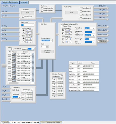
Hardware look:
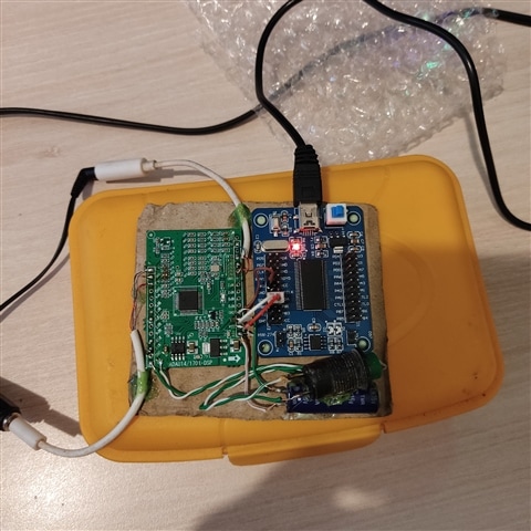
physical board and programmer connections (not the greatest job, but enough for testing purposes i guess ):
Will be really happy if someone with more experience could point me into the right dirrection, thank you!
** Update 4 hours or so later **
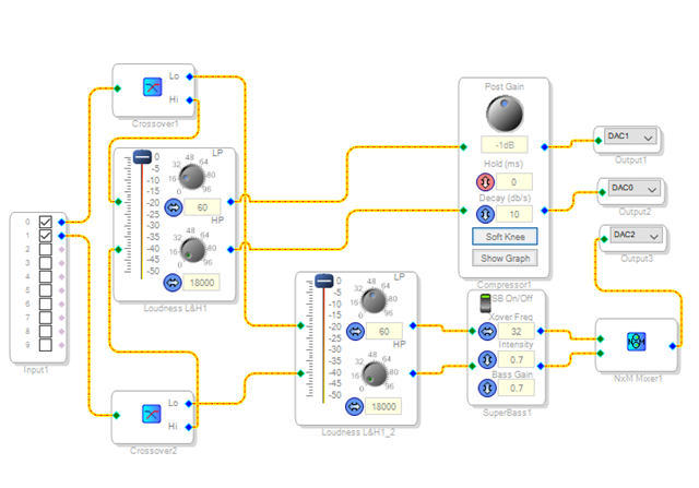
I attempted to reach my desired goal in sound by this new Scheme, omitting DynamicBass block:
but still it does not start to play DSP'ied analog sound to the output from the input. I suspect something is in the software side, because as previously i noticed, that compiled programm is not ereased upon power cycle, its just
that it seeems that analog inputs or ADC isnt starting up as it should...
Edit Notes
A little bit more info
[edited by: AntonioColombo at 7:59 AM (GMT -4) on 27 Sep 2024]
Audio Signal Processors
software
adau1401
SigmaStudio 4.7 Beta
SigmaDSP Audio Processors
adau1401 mini DSP (green board on aliexpres/ebay etc)
Show More
Hello Antonio,
Thanks for the detail in your post. It is helpful to get an idea of what you have done and what you are seeing. You are my eyes and ears in this process.
I want to mention that you did get me to smile today. Here is the quote:
AntonioColombo said:
ChatGPT suggested to add delay block right after analog inputs and processing blocks, so in order that mcu has enough time to initialize everything, but i failed at this too, what is the right way to do it, and would it actually help in my case?
This is funny because ChatGPT has no idea how this all works and how SigmaStudio works. Adding a delay is funny. This has ZERO effect on initialization of the DSP. Here is how it works:
I will start with selfbooting if this is working which I will discuss in a minute. But, SigmaStudio does the same thing as the selfboot state machine does. You can see it in the Capture window when you link compile download.
(I will skip a few steps like setting up the PLL)
The registers settings are transmitted to the DSP.
The default (according to settings in your program for default like volume settings and EQ settings etc.) parameters are transmitted and loaded into parameter RAM
The program is transmitted and loaded into program RAM.
Then SigmaStudio starts the DSP running.
The DSP program is run every sample period and then waits for the start of the next sample period. So what you see in the SigmaStudio schematic is run every sample period. This is why the delay is funny. The program will usually start by picking up the latest sample from memory and starts processing it. The latest sample is what the ADC deposited into a certain memory location.
Have you watched some of my introductory videos on the YouTube channel? I do need to make some regarding Selfboot but things here at work have been hectic and my personal time on the weekends have been busy with other things as well. I make those videos on my personal time.
I suggest you start really simple. Do away with all the bass processing blocks like loudness and Superbase etc. Just send the LF output of the crossover to the subs.
Another thing I suggest which has nothing to do with the problem but has to do with saving instructions is to get rid of the NXM mixer and just use an addition block to add the two channels together. This will add 6dB for signals that are on both channels so you could use the Signal-Merger which also lowers the sum by 6dB but I think a simple sum is fine.
Selfboot.
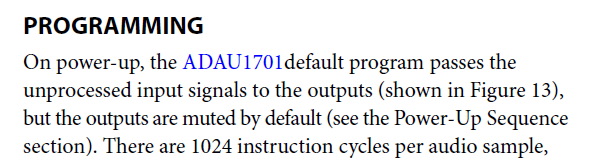
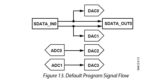
This part has a default power up mode. I think this is what might be happening.
In a way I wish this part did not do that. All of our newer SigmaDSPs power up doing nothing if no program is loaded.
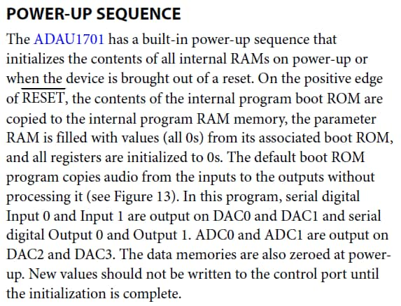
So I suspect the EEPROM is not being loaded and you have the default program loaded.
So why would the EEPROM not be loaded? It seems like you are correctly programming it. You are testing it and it is checking out OK.
So I will assume it has the program loaded correctly. I have no reason to doubt that based on your tests.
So the next thing is for Selfboot to work the Selfboot pin must be high when the part powers up and comes out of reset. (the reset pin has to be high or go high)
I just ran into this two days ago with the Dayton Audio eval board. The board links the EEPROM Write Protect logic line with the Selfboot logic line. So when you plug in the programmer you ground the Write Protect pin which allows you to program the EEPROM however, it will disable the selfboot. So for the Dayton Audio board I HAVE to remove the programmer and then power cycle and it boots up fine.
The Dayton Audio KPX programmer has a switch to allow you to let the part selfboot but I wired an adaptor cable so I could use a USBi and so my setup has no switch to un-ground the selfboot pin. (let it be pulled up)
These low cost boards are great but they never come with schematics so you can figure this out!! I suspect that the selfboot pin is being held low so it is not selfbooting.
Dave T
Dear Dave,
I am sincerely amazed and also thankfull for your kindness to provide the knowledge even for novices like myself!
Regarding ChatGPT, it was my desperate source to find information, since i am more accustomed to avr micro-controllers and arduino platform, this whole DSP experience is a whole new level for me as a hobby electronics thinkerer, so the information You kindly provided helped me better understand some principles of how adau1401 chip works, and quite frankly, it is amazing! ( I have a LOOOOTTTT to learn about it, but small steps, right? :) )
Eventually i managed the board to boot up, but i needed to sacrifice some blocks in schematic, also, even chatgpt was giving me hints about selboot pin from the IC, but as rightfully You mentioned, i dont have a selfboot pin provided on mini circuit board, all i have is WriteProtect, which is not the same. While doing experiments, i also noticed, that when i want to write programm from SigmaStudio into Adau, i need to pull WP pin from the chinese board to ground, and then after programm has written, i can break connection to ground from WP pin ( hence why i added a little push-button for experimentation purposes).
ChatGPT was also hinting me, that by adding some heavy blocks like Dynamic bass, it might overwhelm the chip, but I dont know if that is truth.
Next I will try to learn more basics about how these chips operates. Unfortunatley, I was not able to locate Your channel or videos of explanation for these chips, maybe You could send me a link in PM or here, if that is appropriate?
With utmost respect,
Antonio Colombo!
Hello Antonio,
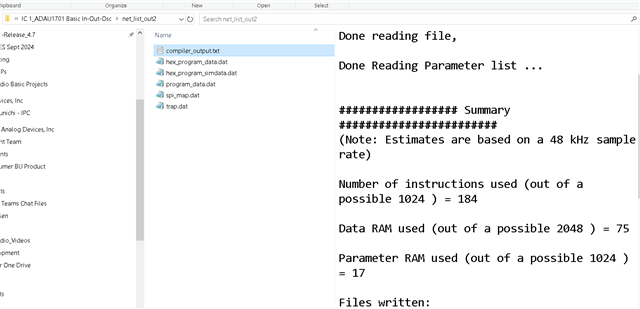
The newer SigmaDSPs we have will output a usage report into the Output window in SigmaStudio but this feature is not there for the 1701. To look at the usage of instructions you have to look at the compiler report file.
When you compile a project, you will see that SigmaStudio creates some folders in the same folder that the project is located in. There is one called IC1. I will assume that the ADAU1701 is IC1 in the schematic. So in that folder is another folder called net_list_out2 and in that folder is a text file called Compiler_output.txt. In there you will find the info. Here is a screenshot from my computer:
You cannot get a program all the way to 1024 because there is a little overhead for things like safeload. So once you get to 1010 it can be iffy,
My YouTube channel is here:
Channel Welcome Video! (youtube.com)
Note that with the Dayton Audio board I have here that I have done some projects with does link the WP pin with the Selfboot pin. Without the schematics you are never 100% certain but I figured it out with experimentation.
I suspect your board might be similar.
Dave T
Please log in to reply.