External Master Clock vs I2S
Using ADAU1772, we create a Master Clock with our fpga. It is a little off, 12.262 MHz. I did not change anything in the PLL SigmaStudio tab, wrote the EEPROM with the fpga, and we got the intended sinewave out! Yea!
However, the sinewave stream was broken into a big segment followed by a space, followed by 7 more smaller segments with space in-between, in a stream. We checked all our clocks etc. and didn't see anything strange with a scope. Can't get to the I2S data to check very easily but looked ok when audio output was zero. So I'm thinking I should program the PLL page - our frequency really was 12.262 Mhz. So I did that but then things got crazy. Using the eval board, I compile/download using the icon, erase the EEPROM, write 1772 compilation to EEPROM, and then go to write EEPROM to a file. I create a new location for the new files but I could not get the utility to write them there. Typically it would write a BIN and HEX file, right? It would put up a file upload page but leave open the filetype - nothing to pick so I entered BIN, click on write to file and nothing happens. Seems the only folders/files that work have a prefix or suffix "IC-2". Perhaps the rule is if you change anything in the project configuration you need to save it as a new project? I'll try that tomorrow.
Questions:
1) Is it likely me not inputting the real MCLK frequency caused the interrupted sinewave stream?
2) right click on the 1772 in the configuration and besides "write compilation to EEPROM", there is a write address/data and write sequence. Could you explain when/how these are used?
3) Could you write a bit about the file structure the programming tool relies upon? It turns out the tool was writing a BIN and HEX file to another (older) directory - not the one I was trying to force it to populate. Probably overwrote the files that I had there originally.
hardware
ADAU-1772
eeprom programming
Integrated/Special Purpose A/D Converters
pll
Audio CODECs
Show More
Hello bklein,
There are a number of things you brought up. I will probably not get to all of them but I will start somewhere.
On the configuration window in the project you drag in the EEPROM GUI object and connect it to the USBi. There it gets assigned an "IC" number. Often it ends up being IC2 but it could be another number. When you have an EEPROM in the project this will signal SigmaStudio to create a folder for with the IC number in the folder name. So IC2 will be in the folder name. In that folder you will find the hex file for the EEPROM. This is the file to use to load into the EEPROM if you use your own EEPROM loader. The other files are part of the compiler output and they are useful but not for directly programming the EEPROM. They are more geared towards loading it into a microcontroller for it to program either the DSP or the EERPOM. But it requires custom code.
Regarding MCLK frequency.
The frequency being a little off will NOT cause the problems you are describing directly. There might be a reason in the system that I am not aware of but it should really not be the cause. Here is why I say that. Here is an example,.. If you use a 12.288MHz crystal and you set up the PLL correctly for the 256x fs settings, then when you select the internal fs of 48kHz you will get 48kHz. 12.288MHz/256= 48kHz.
If you change out the crystal for an 11,289,600Hz crystal. Then when that gets divided by 256 you will get a 44.1kHz fs in the DSP. This is how you set it up for 44.1Khz fs. You simply use a crystal that is 44.1kHz x 256. So you using a slightly lower frequency of 12.262MHz means your internal FS will be 47.898kHz. Just a little off.
The serial ports in this part all go through sample rate converters so this part will operate well and seamlessly in most systems if you operate the serial port as a clock slave. If it is a master then the FS from the internal clocks will be off if there is something in your system operating off of another master clock that is exactly 256x fs. So this might be your issue but I would need a lot more system details.
I should mention a hardware bug in this chip. From what you described I do not think you ran into this. If you use the CLKOUT pin to drive an external codec or something else in the system then you may run into this. If you setup the serial port to be a TDM output and you also set it up to tri-state the data line for unused channels, then what happens is that the CLKOUT pin is also tri-stated during unused serial data channels. It is somewhat of an illogical bug that does not seem like it could be related but it is.
What is your data flow in your system? How does the FPGA interact with the system?
This part is usually best to operate on its own crystal or an MCLK like you are using. Setup the converters to run at a high rate like 192kHz and then operate the serial port as a clock slave so the ASRC will convert everything to the FPGA rate or from the FPGA rate. So the crystal frequency you have would work fine. The internal rate would be just under the nominal but that is not a problem. The ASRC will handle the rest. The PLL loop filter will still function fine and you can setup the PLL to operate in integer mode.
Dave T
What are the implications of the CLKOUT bug? We will be using that pin for I2C - as you pointed out we can't mix everything in the core as not enough inputs. 4 analog inputs summed or streamed out ADC_SDATA to the FPGA, SDATA back out the FPGA to the 1772 serial in DAC_SDATA and sent to the L&R ADC's.
Creating a new project after changing parameters on the old one solved our problem of getting programming files. The utility will not allow me to declare a different location for them than the default.
We have been experimenting with MCLK frequencies from the FPGA and settings in the PLL tab. We see the output (sine) signal stop, followed soon by a small glitch in the MCLK. It would make sense if it were timed the other way around...We played around with the PLL on the eval board but since it always has a 12.288 MHz from the APX we can't realistically test our issue with it. I don't see a way to minutely change the MCLK frequency in the APX for diagnostics like this.
Are there interactions that must take place between the FPGA and 1772 that I should be aware of? We seem to be able to program the e2prom on the board successfully. Just
We see the output data stop before a glitch occurs in the 12.288MHz CLK OUT (MP6). The output signal soon resumes but ramps in amplitude (not abrupt).
Barry
I think we now see the source of our problem - the I2C bus is bring driven when the audio out dies. Not supposed to be anything happening there....
Hello Barry,
I must admit I am getting a little confused as to what is going wrong at this point and what you are trying to accomplish. First, I want to clarify that in this past two posts you mentioned "I2C" which is a communications protocol not an audio data transfer protocol. I think you meant to write "I2S" Why would you need to use the CLKOUT when you could just distribute the MCLK that is going to the 1772? Yes, sometimes it is good to divide it down for other reasons.
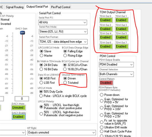
Are you planning on using TDM-8 and having one 1772 drive four channels and the other 1772 drive the other four channels? If that is the case then you will have to set the serial port to tri-state during unused channels and that is the mode that screws up the CLKOUT signal. That is when this bug would be a problem.
bklein said:
the I2C bus is bring driven when the audio out
So do you mean the SDATA pin is driving zeros when the audio dies? Define "audio dies". If all the clocks stop then the part will sit in the state that it was last in. If you are getting clocks and just not sending audio into or muting the output then it should drive zeros. If you need to set it up like I described above where the SDATA pin is only driving during the four active channels then you need to set the registers up for that.
That would be done with these register settings:
Dave T
Hi Dave,
I'll be sending you an email with info.
Please log in to reply.