Latency
Hello,
The aim of my project is to implement an ANC system for noise cancellation in ducts below 300Hz, so the reference and error microphones can be placed at big distances (1m for example = 3ms delay). However due to setup limitations, the secondary path is around 0.4m, so finally the maximum latency I can have with my controller is, lets say, around 1.5 ms.
In other hand, the duct creates resonances and also the secondary and feedback paths must be well determine. So I need several instructions in order implement the adaptive filter as well as the two FIR filters for S and FB, this is FBFxLMS.
As I experimented with the FastDSP, the T peregrine block crashes SigmaStudio, so I decided to use the ADC directly to the FastDSP at fs=768kHz, decimate(Fdec) to 12kHz in the SigmaDSP and make all the algorithm, and finally interpolate(Fint) to 768kHz to the DAC. In this way I think I can have low latency in the I/O and enough available instructions for the filters. Is this guessing right?
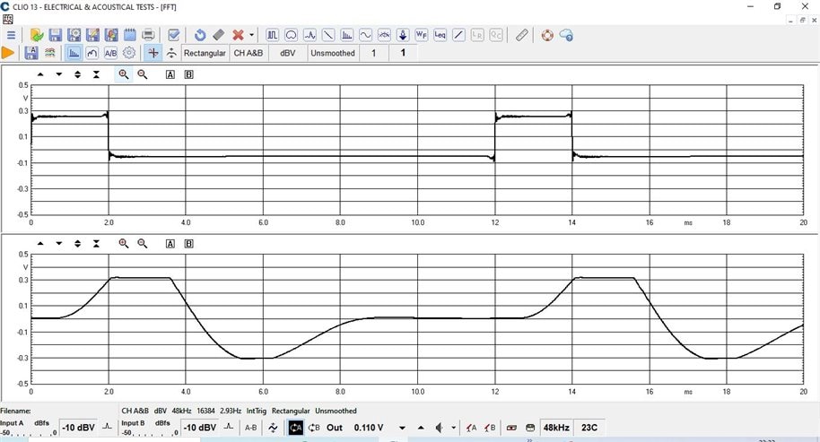
With this panorama, I ask myself which is the latency of the DSP, and I started to measure it. As it is an LMS algorithm I do not know if this is more tricky than usual... --> I send the same signal to the reference and error inputs, so my guess is that the output of the DSP should be the same signal without any phase shift (or delay), and the delay measured in the output is the latency of the DSP itself (correct me if I am wrong). In this measurement I eliminate the secondary and feedback FIR filters to avoid the delay they can introduce.
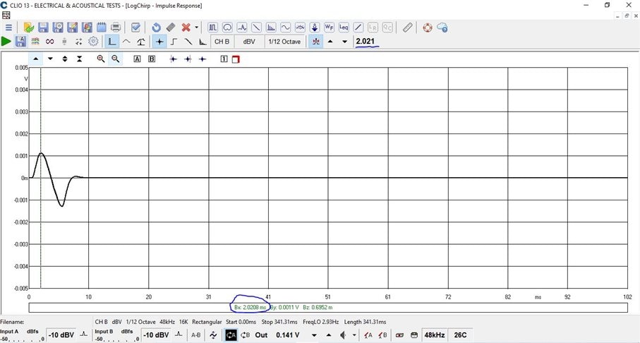
I used different test signals: pink noise, pulses, sinus tones at different frequencies... and I get approximately 2 ms latency in all the measurements with LPF and 1ms without LPF (I was using Low Pass Filter at 300Hz to avoid undesired high frequencies in the algorithm so I think it was the reason of this latency shift). Anyway, and looking at the datasheet, I was expecting much lower latency of the DSP... like 0.1 ms or less. Is this right?
I attach some pictures of the measured latency, as well as the SS project. Please tell me if I am doing something wrong, if this latency is the expected one (and in this case how could I reduce it?) or if the latency should be much lower as I said...
LMS_768kto12k_latency.dspproj
Latency with 2ms pulse (LPF active). Up:Input. Down: Output. Measured latency: 2ms
Latency with 2ms pulse (LPF removed). Up:Input. Down: Output. Measured latency: 1ms
Latency with PinkNoise (LPF Active). IR. Measured latency: 2ms
hardware
ADAU1787
Integrated/Special Purpose A/D Converters
Audio CODECs

Hello
Where is the FIR filter being implemented? In the SigmaDSP core? Because an FIR filter is a block based filter so it has to assemble a block of samples thereby adding a lot of latency. The filters in the FastDSP core are IIR filters and that core cannot do an FIR filter.
I am responding here without looking at your project. I will take a look at it and make further comments later.
Thanks for including the project!
Dave T
I removed the FIR filter because of this, just to see the latency without any FIR filter. The plots and results I showed are without FIR.
DaveThib any suggestions?
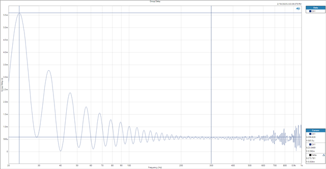
I took a look at your project and found a source of the issue the project is experiencing clocking issues. It is not obvious but in SigmaStudio to pass the ADC to the decimator the ADC does not need to be in the canvas. What should be done instead is to route the ADC directly to the FDEC (FDEC_CTRL -> FDEC0_ROUTE0 and set to ADC2 and do the following for ADC3).Now the canvas won't have any ADCs on it this leads to the second change that you need to make the clock source for the FDSP FINT01. The FDSP rate source needs to be changed from adc23 to FINT01 (FDSP_CTRL->fdspctrl3->FDSP_RATE_SOURCE->FINT01). When I put a sinewave signal into the two ADC inputs I had the signal gain keep going up until it clipped. The simplest way I found to measure the latency was to delete the adaptive filtering blocks then measure the audio pass through. At ADI our delay specs are measured based on the group delay at 1kHz. I measured on the project "LMS_768kto12k_latency_adaption_removed" group delay at 300Hz because that was the upper frequency that you wanted to analyze and found at that frequency the group delay is 500uS. However, the group delay is non-linear due to the processing. I have attached the group delay plot for your convenience. I also have attached the projects with the changes.
LMS_768kto12k_latency_revision.dspproj
LMS_768kto12k_latency_adaption_removed.dspproj
Dear PhenixNunlee
Thanks for the suggestion. As you said with the adaptive filtering you need to adapt the input level in order to avoid the system unstable (step size value). What I used to do is to adapt the volume control and see the output signal before clipping and stable, then measuring the delay. However thank you for the advices, I will try the routing suggestions and check for the latency with all the blocks included, as I guess they will increase the total latency.
I will be back with the results.
Dear PhenixNunlee
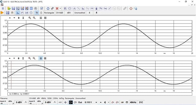
I tested your suggestion and now the latency is around 0.4 ms (attached file). So thanks for that. However, I would like to add some LPF in the input of the ADCs in order to avoid undesired high frequencies interferences in the LMS algorithm. I am thinking to implement IIR block filter in the fast DSP for that purpose. Do you think with this configuration I can implement it? Or as we set the ADC to not be in the canvas is not possible? Also I could use this IIR block to simulate the secondary path...
Best regards
So, you can just put the LPF filter before your LMS section that should work fine on the Sigma. You don't need to put it in the FDSP Because if you drag the ADC and put a filter and then send it to FDEC you're going to have similar issues with clocking. Putting it in the FDSP is just moving the filter before the decimator.
Please log in to reply.