CLKOUT BCK not aligned
Hello
I have a problem connecting adau1452 with a digital AMP chip TAS6424. When playing, TAS6424 reports a clock error. Finally, I figured out that CLKOUT as MCK is not aligned with BCK and WCK. I am asking if there is any way out of this?
cause I'm going to downgrade adau1452 to adau1701 for cost saving issues.
Best regards
Power Pan
Audio Signal Processors
adau1452
hardware
SigmaDSP Audio Processors
Hello Power Pan,
Could you tell us how do you verify that the CLKOUT and BITCLK signals are not aligned?
PowerPan said:
Finally, I figured out that CLKOUT as MCK is not aligned with BCK and WCK. I am asking if there is any way out of this?
Are you reading the clock fault detection bit in your DAC? or did you verify with scope or other measurement tools?
It seems like that DAC is complete slave, so it needs MCLK and serial clocks to be provided. And you are using CLKOUT pin from DSP as the DAC's MCLK and serial output port generates the serial clocks to the DAC, so both clocks are generated by the DSP. thus, there won't be an issue. Many customers have used this way of clocking, and we do recommend this, and we have never come across any problem.
There might be a chance of them not aligned but the number of MCLK transitions within LRCLK/BCLK will be evenly divisible, so it won't create any audio distortion. Because most of the codecs only need X transitions of MCLK and the phase relationship of the MCLK edges to the LRCLK edges are not important.
Are you facing any kind of problem with this?
Also, note that the 'CLKOUT' pin is not designed to drive long cables or other high impedance transmission lines. Use the CLKOUT pin only to drive signals
to other integrated circuits on the same PCB.
Could you please share more details about your setup so we can better understand the situation?
Regards,
Harish
First I try to use 6424 as the amp from DSP digital output, and tas6424 always reported clock error, dso, check with oscilloscope, and found the CLKOUT were not aligned with BCK, but BCK did aligned with WCK.
Hello PowerPan,
As I mentioned earlier, the MCLK edge is not required to be synchronized with the I2S signals, only that the required number of edges happen during one LRCLK period. (one frame). Remember that we use an internal PLL for the clock reference and that it locked to the MCLK frequency but not the exact edge.
However, if you really want them to be aligned, then you can do one thing. I propose you use the BCLK pin of either an unused port (it can be an input or output), or a port that is set to TDM8. You set that port to be a master at 48kHz and it will produce 12.288MHZ that is aligned with the edge of the LRCLK. You can use this BCLK as CLKOUT to slave devices. You can even adjust the polarity. You have control over it and can gate it if desired. I think this will solve your problem as long as you have an available port.
Regards,
Harish
Hello Harish
thanks for the advice. I did use another bck as mck for AMP, but that's for ADAU1452, no other BCK available for 1701, that's the issue. So I need advice for that.
Best regards,
Power Pan
Hello Power Pan,
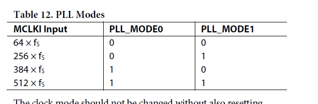
I looked at the amp datasheet and it can accept an MCLK frequency of 128x, 256x,or 512x fs. It is a four channel amplifier. It can also accept TDM4 or TDM 8. I was going to suggest you use TDM4 but in going through the math there is no 128x setting for the PLL which is a problem.
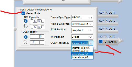
In your case just setup the 1701 to output a TDM8 signal with 32 bits per channel slot and you will have a Bit Clock frequency of 256x fs. So use the bit clock to go to the serial input and also to the MCLK input pin.
Setup the MCLK pins to also be 256x. This is in hardware not software.
So with a sampling frequency of 48kHz you need an MCLK input of 256 x 48k = 12.288MHz.
TDM-8 signal with a sampling rate of 48kHZ and a channel slot of 32 bits give you a bit clock frequency of 32 x 8 x 48k = 12.288MHz.
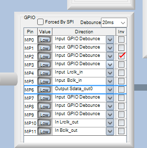
Here are the register settings:
MP-11 is the bit clock. MP-10 is the LRCLK and MP6 will be the TDM data out.
Here are the serial port settings:
Since you only need four channels it would be good to use TDM4 but the problem is that will generate a 6.144MHz bit clock and there is no PLL setting for a MCLK in of 128x fs. Which is unfortunate. Because, the lower frequencies are easier to mange on a PCB layout.
Then of course you have to setup the amp to accept the TDM-8 and the correct channels of the 8 channels.
Dave T
Hello Dave:
I asked the other engineer, MCK=BCK=12.288 will work, so, this problem is solved. thanks for your suggestion.
Best regards,
Power Pan
Please log in to reply.