Conditioning/filtering of noisy AUXADC input
Hello EZ,
I have build a DSP using the ADAU1466. It has been working great for a while know. However, I have mooved it to a new case with a significantly longer wire run for the potentiometer that is used for volume control. In turn i have gotten a significant amount of noise on the AUX input whcic is audible in the music.
I know I have to change some things here hardware wise in the next revision, to ensure a better supply for the AUX ADC's and maybe shielded cables. I haven't really been giving enough care to this section of my hardware design..
But anyway, this is how it is for now. Is there any good tips to reduce the impact of the noisy signal from the potentiometer? I have tried increasing slew rate of the volume control, which helps, but even at max slew rate it is still slightly audible. Then I tried adding a 2., 4. and 6. order low pass filter at 100 Hz to the aux input. This also helps and lets me reduce the slew rate again. But I cant help to think that there may be better ways to do this? Or is this okay? I am very new to Sigma Studio still.
Audio Signal Processors
adc
1466
software
adau
sigma studio 4.7
aux adc
sigma
noise
1452
volume
studio
SigmaDSP Audio Processors
adau1466
Show More
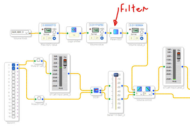
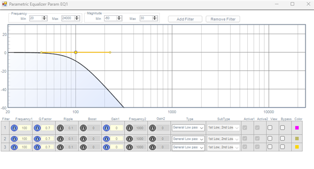
Hello DannerD3H,
I haven't seen anyone putting a filter in AUXADC input path which is usually used to control the volume of the audio signal.
DannerD3H said:
In turn i have gotten a significant amount of noise on the AUX input whcic is audible in the music.
I'm not sure what you mean it's audible in the music. The AUXADC is a 10-bit ADC which will output a number between 0 to 1023 and when you left shifted 14-bits then it will be 0 to 0.9998 (in 8.24 decimal) which will be used to control the volume. if the input is 0, then the input is multiplied by zero so the audio will be muted, if you put the pot in mid-way, it will give you 0.5, so the audio is 6dB down, when you put the pot in Full CW, then it's 0.99998 (almost 1), the signal will be multiplied by 1 and will pass 'as is'. if you set the pot somewhere like 1/3rd of the pot rotation, then it will give you 0.333 almost constantly (a few LSBs may change), your audio will be scaled with 0.333 which is around 9.5dB down. The auxadc will affect the gain factor of that vol control module and it will not introduce any noise into the actual audio.
Do you think the AUXADC input is changing so fast in a way that changes the gain factor of the volume control block undesirably?
Have you tried LUT approach?
could you give me some more info to work with?
Regards,
Harish
Hello Harishgowtham,
Thanks for the quick reply.
The AUXADC value is so noisy that it is clearly jumping up and down on the readout block. Adding the filter pushes the noise out to the 5th decimal in the last read out.
This noise is very audible without the filter, and still is with low slew rates on the volume control block, although not as bad as without the filter.
The noise is most audible when the potentiometer is almost at 0, up to maybe 1/4(At low platback volume and low voltage on the AUXADC input).
The audible effect seem to be exagerated by bass-heavy content.
I suspect either the main PSU, or my power delivery to the AUXADC part of the DSP chip itself is too noisy. Or maybe the long wires from the potentiometer to the DSP board are picking up noise from the 220VAC-12VDC supply in the same case.
Either way, I am working on a new PSU and a revised DSP board where I will pay greater attention to this part.
However, For this specific DSP board I need to find a solution that works. This seems to do the trick, but was wondering if there was a better/more correct way of solving the issue. Or if there is anything obvious I need to pay attention to in my next hardware revision. Such as stabillity of the AUXADC Supply or similar.
What exactly is the LUT approach?
Harishgowtham said:
The AUXADC is a 10-bit ADC which will output a number between 0 to 1023, in 8.24 decimal, it will be 0 to 0.9998 which will be used to control the volume.
Why do I then need the logic shift to get it to output a 0 - 1? Is there maybe something else seriously wrong here hardware wise?
The program shown above behaves like this when the volume knob (10k linear potentiometer) goes from min to max:
The first readout after the AUXADC input always has 0.000000X. X goes from 0 - 1 (need to double check this)
The readout After the logic shift goes from 0 - 1 (thats for sure). But with significant noise
The readout after the low pass filter goes from 0 - 1 with the decimals after the 5th jumping around
The output volume goes from muted to full volume, with the majority of the volume applied over the first half. This is understandable as the pot i slinear and I haven't yet managed to add a lookup table to give it a logarithmic behaviour.
There is no audible noise at slew rates above 4.
I previously had the same DSP board(and DACs) in a differnt case with a different potentiometer (still 10k, but with much shorter wires) and a different PSU (USB-C PD). This setup had zero issues. Only now in the new case the issue arrised.
Is there any other info specifically you need?
Cheers, Daniel
Hello Daniel,
The reason for the logic shift is because the 10 bit output is right justified to go from the LSB to the 10th bit. Well, the volume controls want to see an 8.24 number. A full scale 0dBFS setting for a volume control is a 1.23 number. So a "1" in the "1" MSB position and 23 zeros to the LSB.
Well, if full volume on the AUXADC is a ten bit number right justified it is nowhere near a high enough number to get to be 1.0 for 1.23 number!
1.23 number is a 24 bit number. So if you left shift the AUXADC output by 14 bits then the MSB of the AUXADC will match up with the MSB of the 24 bit 1.23 number.
Now, I think this noise is good old analog noise issues. So the power supply is a big factor and how clean is the AVDD and how clean is the ground?
Then how long are the wires to the pot? What are the wires going by on the way to the pot? Did you twist the ground and power wires together that is going to the top and the bottom of the pot? Usually also including the wiper wire in the twist is also a good idea. These are all good old analog design and implementation stuff.
How far from the DSP is the place where you are connecting power and ground? That is also a factor but I have no idea any details of your PCB.
Your experience with a different power supply is a big clue for all this. Now, it could also just be a faulty or low cost power supply. I have seen that before with some pro audio gear I have serviced in the past. The switching frequency is no longer very high and it is in the audio range messing with the along and ADC conversions.
Dave T
Hello again DaveThib
Thanks for the explenation of the logic shift.
I also think the issue is simply bad analog design/wiring for this part of the board. I was just seeking advice on how to handle the problem best.
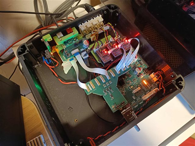
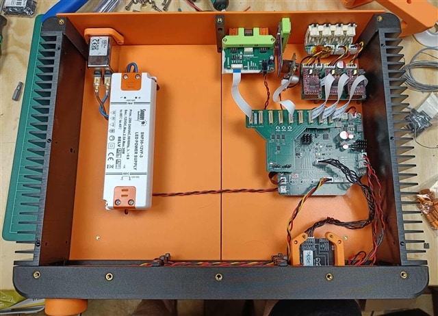
To give some more insight. This is what the old prototype looked like:
And the new prototype looks like this. The Yellow, RED, and Balck wire bundle is the potentiometer wires roughly 35 cm. The potentiometer wires run along the top of the case and the red and black LED wired run along the bottom (Spaced 45 mm apart):
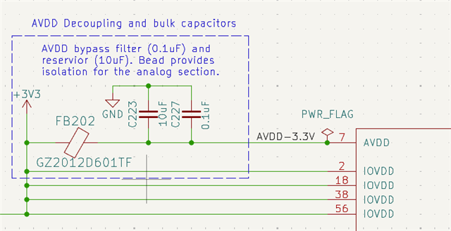
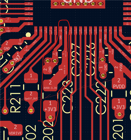
The AVDD pin is simply running on the same 3.3V LDO as the rest of the DSP board but isolated with a ferite bead:
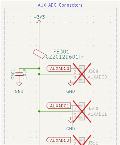
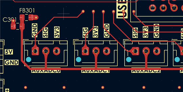
The potentiometer is then connected like this:
For the next version I may use a seperate low noise LDO to power this whole section above instead of this approach.
The main reasons for the new case are:
Accomodate 8 XLR outputs, 2 XLR inputs,
Mains power input and a new PSU design. The Snappy PSU mounted here is a 31USD 10+ year old psu I had lying around. It is only temporary. The previous prortype used a newer GaN USB-C PD adapter.
I am working on a new PSU based on some MeanWell IRM modules and some LC filteters and low noise LDO's.
Match the size of some Amplifier modules I am working on to allow stacking - (a box with 4 channel of amplification - 2x250W and 2X650W)
Change the design to include passive cooling via heat sinks. The current prototype is 3D printed but all plates will be replaced with CNC alu plates once i know where to put the holes.
However, Music quality is very good even with this crappy PSU. The DAC's are mounted on A PCB with significant filtering and very low noise LDO's powering them.
In my designs I use a 100 ohm resistor on the 3.3v to the pots and a 100n cap to ground near the adc input. I use very long wires to the pots at times (up to 3 feet) and never had noise issue with this layout, even with switchers near by.
Hey djamps !
Thanks for that advice, exactly what I was looking for!
So something like this (C231 - on all adc's of course):
And then a resistor on the power for the pots(R307):
Cheers, Daniel
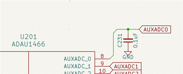
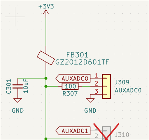
Exactly that. Let me know if it helps!
Thanks for the tip djamps !!
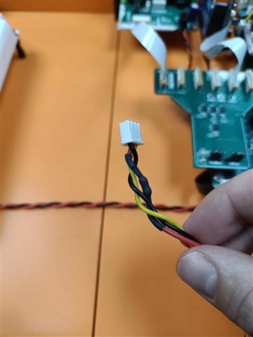
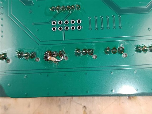
I made a rather cruel rework with a 100 resistor in the cable near the connector and a 100nF cap between the signal and GND pin of the PCB connector
And it works like a charm!
No audible noise and readouts are rock solid :D
Thanks :)
Glad that works... my ham radio previous life made me do it before I ever had an issue. Low pass on the input and high resistance on the source to reduce RF inductance and/or short circuits from killing V+ given my unusually long length of inputs.
Please log in to reply.