USBi programmer issues (EVAL-ADUSB2EBUZ)
Hello everyone,
When we started our DSP project, we got some Chinese USBi programmers with our DSP Devboards, which didn't seem to be of the best quality,
so to improve our reliability we decided to buy the original recommended USBi (The EVAL-ADUSB2EBUZ).
But we are having a hard time making it work...
As far as I remember we got it running once in Sigmastudio 4.7 but we don't seem to be able to reproduce it.
After asking several LLMs about that, we ended up even more confused, as we are supposed to use also the VIO pin which we never used (I think).
Here a link to some tutorial we have used as a reference:
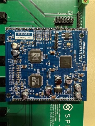
Here a picture of our setup:
With the cheap chinese ones we have reliability issues when logging data back, but they work at least for programming:
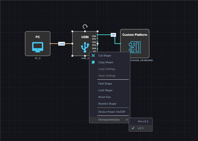
As an additional note, I am aware you have to explicitly choose the firmware version of the programmer manually in Sigmastudio 2.3.
I have tried with both Pre 1.5 and 1.5, and none of them has worked.
So:
Could anyone explicitly point use to the right pinout of the USBi given the devbard we are using?
Could anyone help to figure out what is exactly the problem to program it using the original USBi?
Thank you very much everyone in advance !
Cheers!
Audio Signal Processors
hardware
programmer
reliability
sigmaStudio 4.7
usbi
Sigmastudio+ 2.3
SigmaDSP Audio Processors
adau1466
Show More
Hello raulsphaira,
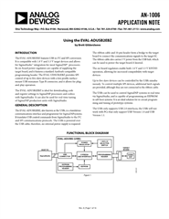
There is an App Note hidden somewhere on our web site. AN-1006. I will drop it into this post for you. It has ALL the details of the USBi.
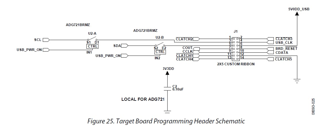
Here is the tricky thing to note. The USBi board itself has a 14-pin footprint for a 14 pin ribbon cable header but we only stuff it with a ten pin ribbon header. The extra four pins are for other SPI latch signals which people rarely need. If they need it then they run wires for it. I have done that perhaps two times in my over 15 years working here. So in the schematics you will see a 14 pin header but in the eval board schematics they are 10-pin.
Here is the schematic for the 14 pins:
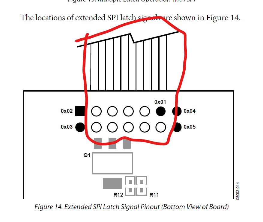
Here is another drawing showing how the 10-way connects to the 14-way:
The two outside pins on each end are not used.
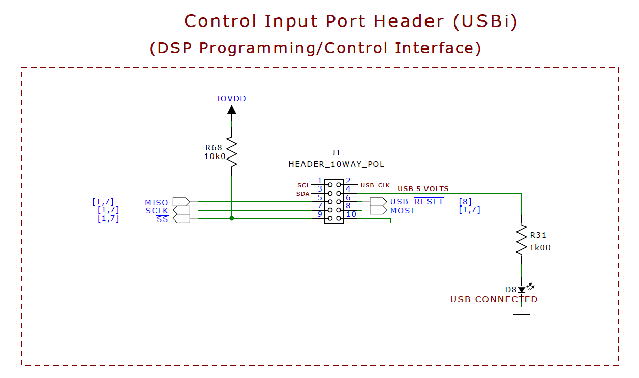
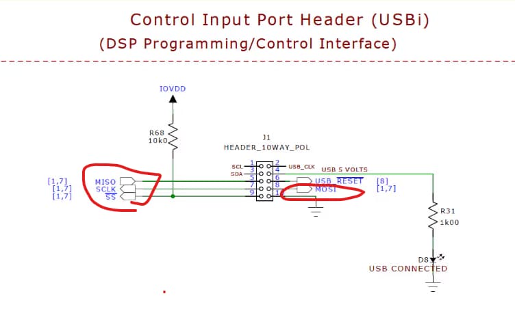
Here is a part of the EVAL-ADAU1467Z eval board that shows you the ten-way connections.
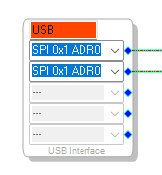
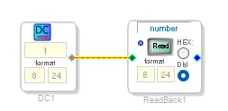
Regarding the USBi firmware revision: SigmaStudio should install the correct driver. On the Config Screen of SigmaStudio, does the USBi GUI show as Red or Green? Here is a screenshot of my computer when I had no USBi connected:
Are you using a PC running Windows or a MAC?
I am not sure where you are seeing the firmware version choice? Rev 1.5 should be the choice. We have been on this rev for a very long time.
This should get you headed in the right direction.
Dave T
Here is the USBi App Note:
Hi Dave,
In regards to the OS: I am running Windows
About the connection:
The USBi is properly detected in Sigma4.7, as far as I understand.
In Sigma+2.3:
I don't think we ever got it running in Sigma+, but I guess we would have to select this option manually.
(The clones actually require the Prev1.5 and they work, even though there are some reliabilty issues when logging data)
Regarding the app note:
We had it already somewhere around, but even with that information I still find it fairly confusing, so I would like to ask explicitly:
What is the minimum set of connections required to flash the device?
As far as I understand:
- I2C_SDA
- I2C_SCL
- GND
- POWER
In my current setup:
Connections to the programmer:
- I2C_SDA
- I2C_SCL
- GND
External power supply:
- POWER
- GND
If this isn't the case I am already screwing up from the very beginning...
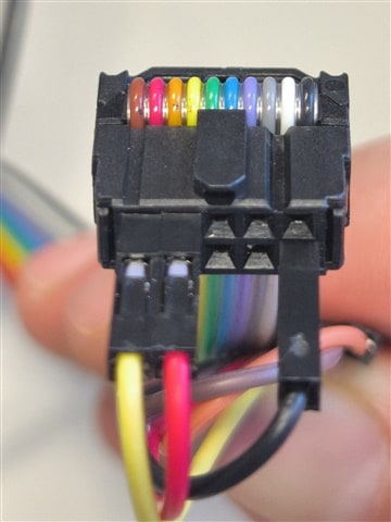
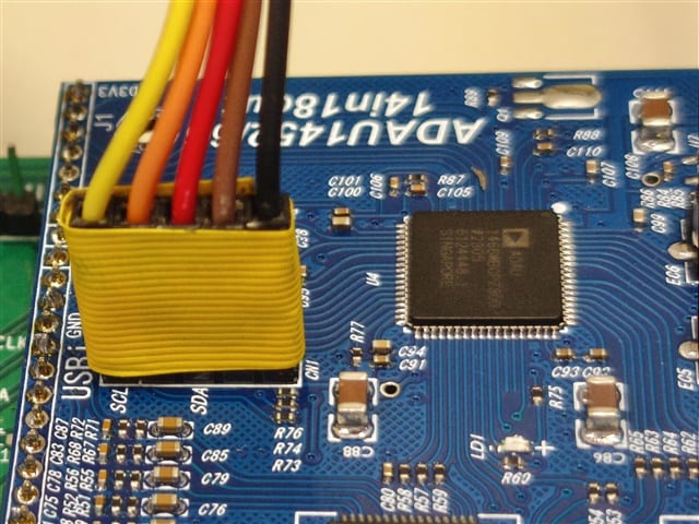
Here a couple of pictures of my connections, which match the application note (I hope):
Hopefully this brings us closer to an answer
Thanks in advance for your help!
Hello raulsphaira,
Thanks for the reply. It was helpful to identify what the confusion is so I can be more helpful.
Excuse me if I am going to get too simple. I am writing this for others who might also be searching for answers.
Our DSP parts and our USBi interface are all able to use two VERY different communications protocols. You have setup SigmaStudio to be the same as the eval board protocol but you are attempting to wire it up for the other protocol. That is the problem.
So now for some details:
The first one, I2C, also called IIC or Inter-IC Communications, only uses two wires, well, it also needs a ground so three wires.
The two signal wires are called SDA and SCL. These lines can go to many chips all in parallel.
SCL is the clock. That is all it is. The clock for clocking in the data.
SDA is a bi-directional data line that transfers a lot of info. It sends an address to tell which part on the bus it is "talking" to.
Then it tells the part if it is reading or writing data to or from the part and which address for the data.
It is a great standard but since all this is happening on one data line it is slow.
The second standard is called SPI. Serial Peripheral Interface.
This standard uses a minimum of four wires.
SCLK, MOSI, MISO, SS
First, I have to mention that there is always one and only one "master" device on the bus and there can be many "slaves".
SCLK is Serial Clock. Again, that is all it does is clock data.
MOSI stands for Master Out Slave In. This is the data that is being sent to the slave device from the master. Only this direction.
MISO stands for Master In Slave Out, This is the data that is being read by the master and sent from the slave device. Only this direction.
SS stands for Slave Select. This is the "enable" line that "tells" a peripheral device that it is being addressed and talked to. There need to be only one device on this SS pin. This is why there needs to be one SS line for each part in a system. This is why the USBi has the four extra pins which are labeled 0x02, 0x03, 0x04, 0x05. So if you count the SS line there are five pins to be able to talk to five different SPI devices.
Now on to your situation specifically:
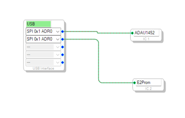
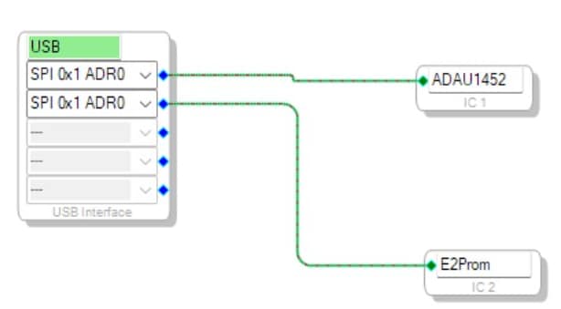
Your screenshot was helpful. This one:
The USB label is green which means the USB system on the computer has "seen" the USBi and has connected it to SigmaStudio. This is great.
Then, look at your settings... You are setting up the USBi to use SPI protocol and the SS address 0x00. This is good.
One of the links you supplied in your first post was referring to the ADAU1401/1701 eval board and that one was setup for I2C. In addition, it was also setup to accept power from the USB interface connection.
I do not have the details for the ADAU1452 eval board you are using but most of those are setup for SPI because of the size of the program files and data. Also, they usually are setup to accept power from a wall-wart power supply not the USBi interface. It normally uses too much power for that.
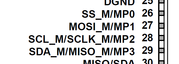
Since these pins have multiple uses the schematics do not always have the full name of the pins which can be confusing. Look at the datasheet. In the datasheet we used both the I2C and SPI names to make it clearer:
Pins 26-29 can be used as multi-function pins so ignore the MPx part of the names.
SS_M means the Slave Select for the Master port. The Slave port on the DSP is where you connect the EEPROM so it can selfboot.
MOSI_M means the MOSI for the master port.
So these first two are only for SPI
SCK_M/SCLK_M means if you have it set to I2C then it is the SCK pin for the master. If it is set for SPI, then it is the SCLK for the master. Both are the clock pins but the names for the protocol are listed.
SDA_M/MISO_M this is the SDA pin for I2C protocol. The data pin. For SPI this is the MISO pin which is the data from the master to the slave parts.
I had mentioned the ground pin earlier for I2C but the SPI also needs to have a ground pin too of course. So you must connect the ground of the USBi to the eval board.
Regarding power, as I said earlier, I do not expect you need to power up the eval board. It is probably getting power from elsewhere, since you mentioned the external pawer supply, which means you would not need to connect the power pin. Although, it will not hurt anything.
So you will need five connections between the USBi and the eval board.
You will not need any of the additional address lines.
In your project, you NEED to have a DC cell and a Readback to test that you are communicating properly. You can delete it later if needed. Watch my video on Troubleshooting on YouTube,
I have this in every project I create.
A few more details:
These are the pins you need to connect to the eval board to make SPI comms work:
Then of course the ground pin.
Then one more little detail. Usually the Reset pin of the DSP is brought out to the connectors. Connect that to the USB_RESET pin. This will allow you to reset the DSP remotely from SigmaStudio. It is a good trick which can be helpful when selfbooting.
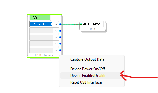
You right-click on the USB GUI and you get the menu that allows you to toggle this reset pin
You select it then it lowers the reset pin. Then it stays low until you repeat this and select it again.
By the way, the Device Power On/Off is for the power pin going out of the USBi. But, this will not apply to you.
Thanks,
Dave T
Hello again Dave,
Certainly most of the things commented should have been obvious already, but actually I want to thank you for being that explicit,
as after being obfuscated with something for a while one can end up not realizing the basics.
In regards to the communication with the DSP:
I have changed the pinout of the connections for the SPI one, and I think I finally understand the layout for the programmer and DSP.
So I2C and SPI pins are common on the DSP side, but in the programmer side I2C and SPI are separate, so the programmer needs to be connected differently depending on which type of communication was set with the DSP (I guess).
Regarding to the different SS pins:
Great! I thought I was limited to the use of a single SPI slave! I don't have a use case for it yet, but it might be useful.
About the different DSPs and evaluation boards:
We may have asked something about the ADAU1701, but we never had an evaluation board for that device.
What we really had:
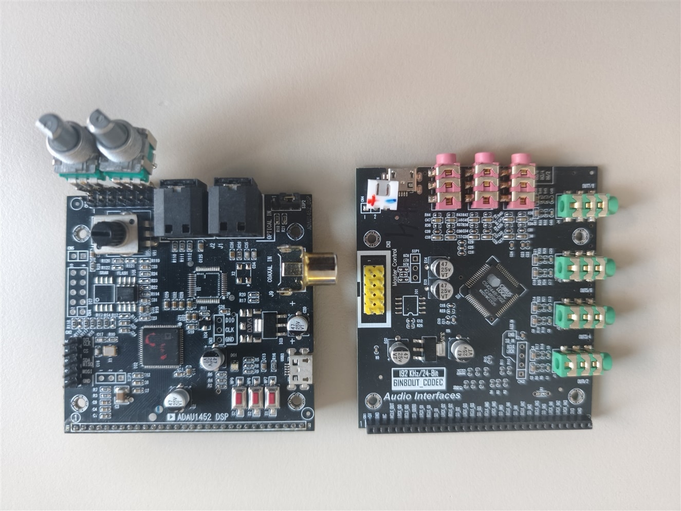
Devkit A:
-
- ADAU1452 in board on the left
- CS42448 CODEC boardff with differential inputs and outputs on the rigth.
(with i2c pinout exposed in yellow for the configuration of the internal registers of the CS42448)
We got these running together and tested our audio processing algorithms over them.
As you can see, the power comes via either the USB of the CODEC board or the JST 0.1in connector near it,
so the board was never powered via the USBi in this setup.
The ADAU1452 has been programmed with both programmers in the past (chinese clone and ADUSB2EBUZ)
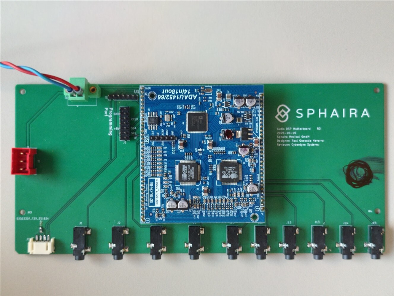
Devkit B:
- ADAU1452/66 (same pinout on both DSPs, only different memory) DSP + 2xCODEC board
(blue, and unfortunately with the CODEC routed single ended)
- Custom made motherboard exposing the audio IO to jacks,and some extras like the auxiliary analog in headers, and power distribution.
As you can see the power for the DSP here comes from the connector on the top left, which is connected to a regulated lab power supply.
Concerning the readbacks:
Before starting with the project, I took the time to see most of your videos,
so actually as a routine I add the readback in all my design files ;)
In regards to the connections:
Thanks for pointing it out so explicitly.
After connecting the programmer properly, I think I figured out what were our two previous issues, resulting in this thread:
- The MISO pin probably was hanging, and that's why we were getting no feedback from the DSP
(and this is what made me try a lot of random stuff until I ended up connecting it as I2C instead of SPI).
- There seem to be issues to get feeback from the original USBi using SigmaStudio+
(I realized I can program the device, and switch on and off the onboard LED of the Devkit B using Sigma+,
but I get no feedback of readings nor DC).
So the current status is:
- The Original USBi:
- works properly with SigmaStudio4.7, and it seems it is way faster with the feedback than the clone.
- can program devices with SigmaStudio+2.3 but it is not able to get feedback.
- The Clone:
- Works with Sigma4.7. but connects and disconnects often. Feedback is slow.
- Works with Sigma+2.3 but connects and disconnects often. Feedback is slow.
Could it be that the reset pin is required by Sigma+ to properly detect the device and get the readbacks?
Thanks for your help!
Hello Raulsphaira,
Gee, here is where I get a little sarcastic and try to act like I have never done anything similar to some of the things you have experienced with these problems. How can you miss something so simple??? LOL. That is why I mentioned some of these things because "been there done that!"!. A couple of times I have been guilty of troubleshooting a stereo receiver and wondering why the power supply seems to have failed only to find I forgot to plug in the AC plug!!! Duh?!!!
So I am happy you have found the reasons and these systems can get complicated so laugh and move forward!!
Now, regarding the last few details you shared for the current status. If you can start a new thread with this if you do not find the reason. I have not had an issue with SigmaStudio+2.3 with regards to the USBi. I do not use it a lot so I may be missing something but the developers of the program also use the USBi so there must be some other reason.... At this moment I do not have any suggestions.
So write up a new post and give me a little time to get through the holiday shutdown backup.
With the USBi clone, that is tough for me to test out since I do not have one. This could be USB driver related and Windows system related... I have not checked to see where you are located. I doubt it is close to my home office.
I do not think the reset pin is the issue. The USBi does not use it often unless you choose to change the reset pin state. It is just a cool feature to allow you to reset the target from SigmaStudio. Generally, SigmaStudio sends a reset command to registers not the hardware reset pin.
I am so glad you have found most of the issues you have been experiencing. You are becoming a power user!! You also gave me some ideas for some new videos. My New Years resolution is to make some new videos. Last year was so crazy busy both at work and personal life. Most of these videos I have made on my own personal time.
Dave T
I have trouble with this board with spi, i2c is working ok if you add i2c pull-ups, on board are 10k resistors its to high 4.7k or 2.2k should be better. you shoud disable selfboot ( I think it is a good idea, need to solder on one resistor to ground if I remember this right the r17 is connected to the selfboot pin) and the Layout seems to make trouble with wiring is to long or routed a bad way. try to add caps 20-330pf, you need to test it on the miso pin to ground in my case it worked most times with this setup. But I would wire up addresses hard to ground and i2c pull-ups and use i2c. This is more stable on this board. Set to firmware in usbi block to pre if you don’t have a 1.5 firmware for me it looks like firmware 1.5 is using fast read and write commands to skip addressing in usbi on every message. Older usbi don’t know it and you get no read ( this is only speculation based on a failed try to use tcpip to flash my adau1452 dev board )
Please log in to reply.