How to view I2C Read data
I am hoping to use SigmaStudio+ to debug the I2C link between an ADAU1463 and DAC chip. I added the I2C Read External Trigger, connected an On/Off button to the trigger input, and connected the output to DSP Read Back, but I can't see the I2C data. I also tried connecting a Graph, but that's probably not the right way to view individual bytes.
Can SigmaStudio+ be used in this way to diagnose DAC I2C Register values?
I realize that I can attach a logic analyzer to the I2C lines and perhaps decode the values from the 'scope display, but I'm hoping there's an easy way to get the SigmaDSP to read 1 to 15 bytes, and then allow the resulting data to be viewed in SigmaStudio+ while it's connected to the running DSP.
Audio Signal Processors
software
SigmaStudio+ 3.3.0
adau1463
SigmaDSP Audio Processors
Hello Brian,
Apologies for the inconvenience, I know it's frustrating.
In the previous version of SS+ 2.3.0, there were some problems with master control port. I don't know whether the same bug repeats here too with SS+ 3.3.0. I haven't tried with this version. But I expect the same bug here which doesn't let the master control port work with other peripherals like CODEC.
Please refer this below link for existing problem with previous version.
SigmaStudio+ Master control block doesn't work (same xml as SigmaStudio 4.7?) - Q&A - SigmaDSP Processors & SigmaStudio Dev. Tool - EngineerZone
You can surely do this in SS, below is an example, I read the DAC register of the CODEC which I programmed earlier to run the codec at 192KHz. Here the read value is 0x4 which is DAC at 192KHz.
I know that the SS+ 2.3.0 doesn't work, so I will try this with SS+ 3.3.0 and let you know what happens.
Regards,
Harish
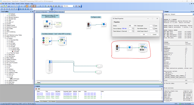
Hello Harish,
Thank you for the workaround. I tried SS 4.7, creating a switch, I2C, and DSP Readback, but it doesn't seem to work.
My hardware is based on the ADAU1463 and uses SCL2_M and SDA2_M pins, which are enabled in the correct settings page. I also set the I2C component to use the correct address for I2C, but there doesn't seem to be any clock activity.
You screenshot is too blurry to read the details, but I think that I created everything correctly.
Hello Brian,
I will attach my project below.
I used the ADAU1467Z Eval board for this, I programmed the on-board codec via I2C to run at 192KHz and read the DAC control register (sample rate) for checking the I2C read.
The expected value is 0x4, and it reads 0x4. (depends on the data length parameter in I2C read module, the value byte will shift in the readback cell)
The ADAU1467 and ADAU1463 are just the same pin configuration wise, so you can try this project.
codec_reg_read_write.dspproj
Regards,
Harish
That project does not compile, complaining "Sequence file not found!" followed by "Master Control Port I/O: ControlPort11" "No data found to load for Master Control Port startup boot object."
I tried to create a new sequence (and just fill it with values for my DAC), but this context doesn't respond when I click New in the Sequence editor.
Can you provide the missing sequence file?
I deleted the startup boot object and was able to compile and download. The 1 Hz Pulse Oscillator works for a brief while in continuous read mode, but then stops working at a certain point. The Switch->I2C Read->DSP Readback never seems to work, whether using continuous read or single-click read.
I suppose that if the I2C were reading an empty bus, I should get 0xFF instead of 00 00 00 00.
Your project seems to have a DC source feeding a register to set the ADAU146x into the mode where it uses dedicated pins for a second I2C interface (which is where my DAC is connected), but I don't understand why a DC source would be used for that as opposed to simply turning on the secondary I2C pins in the general register setup.
Also, I should confirm how the ADAU146x chips handle I2C_M for SCL2_M and SDA2_M. My understand is that the ADAU145x parts must be programmed to use only SPI or only I2C, because they share pins and the mode cannot be changed once set. In contrast, the ADAU146x parts have dedicated pins available for I2C on SCL2_M and SDA2_M, but these must be manually enabled to select them instead of the shared-function pins. My question here is whether SPI and I2C can both function at run time on the ADAU146x parts, or if there is still any sort of built-in exclusivity to these two port types. At this point I'm just hunting for reasons why I2C might not work.
Note that I sometimes see a blip on the I2C SCL2_M pin, but SigmaStudio doesn't show and non-zero data. I will try setting up a logic analyzer with a trigger on SCL2_M or SDA2_M falling low, so I can see whether any I2C transactions are being attempted.
Hello Brian,
The sequence file in my project is used to program the AD1937 CODEC on board, it has the register settings. I wrote those registers into the CODEC and read a register back to show how it works, that sequence file is for AD1937 on my board. Since I don't know what chips are at your master control port, I simply let you add your own sequence file according to your chip registers.
If your chips are from ADI, then you can get into sigma studio >> tool tree and pick your chip, config its registers, link compile download and export the XML file and add it, if you are using other company's chip then there are ways to create the XML file. Please go to the bottom of this wiki page and refer.
Reg the secondary I2C pins and its configuration, I have responded to your new query. Please refer those threads.
Regards,
Harish
Please log in to reply.