ADAU1701 ADC mute EQ
Hi all! I'm new in community and I'm designing a new board using ADAU1701 in self boot mode with E2 no uC saving cost.
I've some questions or better some doubts with Sigma Studio.
1) Sending in ADC an ntc for temperature measurement near heatsink from 0 to 3V, it's possible to reduce gain/out volume progressively and after a threshold turnig on a gpio as pwm to drive a buffer for a fan?
Example: ADC <1.5V no gain reduction pwm off. ADC >1.5V no gain limit and pwm on 0.25 duty. ADC >2.0V gain limit -1.5dB or -3dB and pwm on 0.5 duty. ADC >2.5V DAC in mute and pwm duty 0.75 or DC. Here in the last, I would to like to turn on another gpio for standby function circuit on a board, it will be possible?
2) Using only one push button on a gpio for 4 mode EQ with mux/demux, it's possible to use only 2 gpio for leds saving others 2 gpio for other purpose?
Example: EQ1: led1 and led2 are both off. EQ2: led1 on led2 off. EQ3: led1 off led2 on. EQ4: both led on.
I would like to make the most of ADAU1701 without using micro controller.
Thanks in advance
Cristian
Audio Signal Processors
SigmaDSP Audio Processors
adau1701
Hello Cristain,
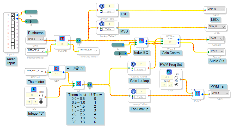
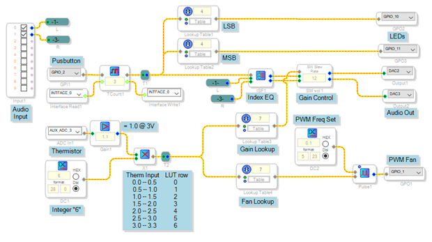
You'll find that SigmaDSP and SigmaStudio are quite versatile and capable of performing these operations. Some of them can be done more elegantly on a Sigma 300 (ADAU1452, etc.) chip, but the humble ADAU1701 self-boots and has internal converters -- making it ideal for self-contained uses like yours. It's simply a matter of getting to know what the available blocks do, and coming up with a combination that works. The diagram below represents just one way of accomplishing what you require.
Your input audio routes first through an Index EQ, which selects from stored filters according to the 0-3 index from the Pushbutton Toggle Counter. You could substitute a different Index Filter (there's several kinds) or go ahead and select from several filter chains with a MUX as you have described. If you can use the Index Filters, however, they save instructions compared to running several filter strings simultaneously while only connecting to one of them.
Two lookup tables (LUTs) also look at the integer output of the Toggle Counter to drive the two LEDs in a binary pattern. The top table's contents of 0,1,0,1 light the LSB LED, while the MSB table contains 0,0,1,1 for the other LED. LUT's use fewer instructions than the logic otherwise needed -- and their behavior is easily changed by editing their contents.
Everything else is driven by the Aux ADC wired to your thermistor. The input math converts the Aux ADC's output to an integer from 0 to 6, which drives two more LUTs to provide the PWM and gain commands. I'm guessing how the Pulse (PWM) block works since its docs are not yet in the Toolbox Wiki, and I haven't yet used it. Doesn't really matter because even if the PWM block won't work at all, there's other ways to achieve a PWM in Sigma-land. Note that the PWM is limited to an audio (not ultrasonic) frequency unless you choose a high sample rate like 96K (with only half the instructions available). For a fan I might actually consider a low audio frequency such as 20 Hz, as its motor will average its own speed. Oops! I neglected the standby function at the highest temperature, but that's just another lookup table and GPIO away. Or a ABCD Comparator and a GPIO. Like I said, there's more than one way to do things here.
Hopefully all this imparts confidence that what you wish to do is achievable with a -1701 and SigmaStudio.
Best regards,
Bob
Hello Bob!
Sorry for my long delay and thanks for your detailed answer!
For my first design ADAU1701 is more than sufficient. For pwm frequency I'm thinking to drive below audio band between 5/15Hz. Now I' m completing my board, I hope will be ready in 1 month to test it. I'll rewrite you as soon the pcb will be ready in my lab!
Best regards
Cristian
Hi Bob!
I've another question: there's a block timer in sigma studio? I.e. if no audio or very low audio on both input I say < -24db, it's possible to set a gpio high or low after 10 or 20 seconds putting external circuitry in stand by mode (power smps off)? However 3.3V is always on. This without uC only self boot with E2.
Thanks and regards
Cristian
Hello Christian,
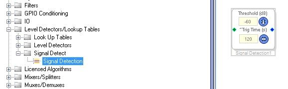
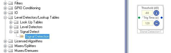
I think the Sigma Detect cell is what you are looking for. If the signal is below the threshold for more than the time it is set for, then it will output a high. Then if any signal goes above the threshold it will instantly go back low.
I think I had an example use of this cell. Here is the location:
I did find my example project. I think this does what you want. You can remove the readbacks, they are there so you can see what is happening.
Dave T
Please log in to reply.