Problem using limiter in Sigma Studio after an FIR filter, as the Limiter gets frequency depenent.
Hi,
I am having problems with a limiter if I use it after an FIR filter, as the limiter gets heavily frequency dependent.
the maximum output level changes wildly with frequency despite being the last block in the chain.
Unfortunately I have no option to use a different limiter block, because of the processing power of the 1702 DSP
i guess it is a compiling problem.
I attach here the preset and the FIR coefficients as well just in case.
The problem is at the HF output.
I did use 3.15 R2 version.
I encountered also other problems but I will ask the question about that in an another time, as it is not that serious.
Would you be so kind and take a look into it? I would really need a good working limiter here....
thanks,
Tamas
adau 1702
fir
limiter
Hello Tamas,
Thank you for posting the project and the coefficients. I will look into it and see if I can find the problem.
Dave T
Hello ttako,
There is a lot in your project that does not make sense. First of all, you are sharply rolling on 90Hz and down on the input then later with the parametric EQ you are booting 85Hz. At that point there is not much there.
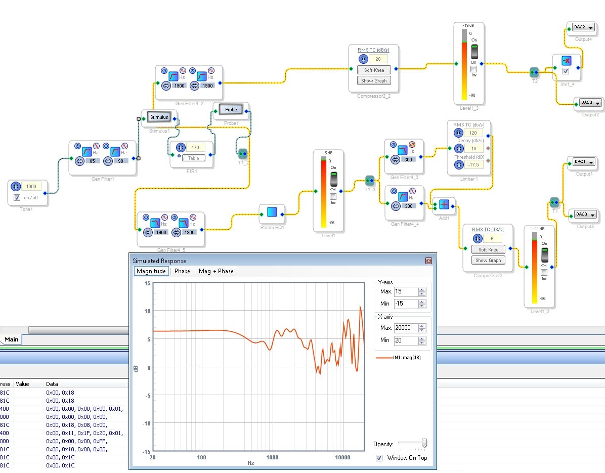
It looks like you are trying to setup a two-way crossover with a further split to limit the low frequencies then add them back together. This is all fine but there are a few details that will cause some wild frequency level changes. This split is at 300 Hz. Below 300 Hz you are inverting the output of the filter then limiting it and then adding it back into the 300Hz - 1900Hz signal. This means that whenever you are anywhere close to 300 Hz you will be getting a sharp cancellation but it will vary with frequency.
Then I ported your project over to a 1701 so it would compile with meters and I could also add some other elements like the stimulus and probe.
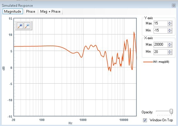
This is the response of your FIR filter:
Is this what you intended?
Here is what the project look like:
Your project compiles using 504 instructions out of a possible 512. This is very close to the limit. There is some overhead of a handful of instructions. I am not certain of the exact amount but it usually seems to be anywhere from 5-10 instructions. So you are on the edge and you may be cutting off a few instructions which can cause unpredictable results. I did not see any of that in my tests.
So I think you should try pairing down the project a little. I kept the FIR filter in there but I do not know what you are trying to do with it. I suppose you might be compensating for the response of a driver.
I setup a project using the 3-way crossover cell that is pretty much doing exactly what you were doing. Including the inversion of the polarity of the LF band. I had to remove the input filters and the parametric filters for it to compile.
For the HP filter tuned to 1900Hz you may be able to use the single precision filters to save a few instructions. The others all should be double precision.
I attached my project. Unfortunately it does not save too many instructions. It uses 496 instructions.
Dave T
Dear Dave,
Thanks for your kind answer.
The question was really about the frequency dependency of the limiter in the HF output.
all other aspects are known and used with a reason. (if you like I can answer your questions, but I do not want to make this post unnecessaryly long)
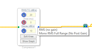
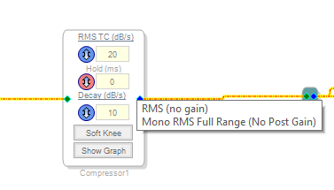
If I use a different Limiter there like this one:
then the limiting will be frequency independent, but I do not have this much instructions availabler in the 1702 unfortunately.
So my questions relies only on the particular limiter in the particular setup.
seemed ma as a bug.
Beside this bug I have found another as well if I use Polarity switxh in the 4th order HPF block right at the input, then it makes the polarity reverse as expected, but as soon as I hit "link compile download" then it changes back to normal polarity!
Waiting for your kind reply,
Tamas
Dear Dave,
Did you have some time to check for the Problem of the frequency dependancy of the Limiter?
Thanks,
Tamas
Hello Tamas,
I have not been able to actually work on this in the lab but I did find out more information. If you are putting in a frequency that is coming close to the nyquist then there are simply not enough samples to accurately determine the level. So we did work on a version that fixes this but I am not certain which one it is. The person who informed me of this said it will say it is peak accurate but I do not see a version like that. I know there are envelope generators by that name but not compressors. Try the "Peak Full Range" version. The only issue is that it will take up more instructions. So you are back to that problem. You may have to move up to the 1701 to do what you need to do.
Sorry that I did not have the time to fully work this out. Let me know how you are progressing and I will work on this more.
Meanwhile, can you explain in a little more detail what you were sending in for signals and what you were seeing on the output? How were you measuring it? This way I can try to replicate it here.
Dave T
Dear Dave,
Thanks for your Answer!
Would be great to see an instruction "lite" good working limiter :-)
Anyway back to your question: We did measure with stepped sine wave (1 sec for a sine ) and did drive the level into limit, and the output of the "good" (with that I mean it worked as we normally would think it works) Limiter gave us a flat frequency response output despite the fact, that the signal path had a very non linear frequency response when the limiter is not there or has no Gain Reduction.
OTOH the Limiter in question did give us the very same frequency response (alrough with a decreased level relative to the input + signal chain's gain) When driven with a signal, which caused limiting and so also good amount of Gain reductions.
For the measurtement we did use the software ARTA with its "STEPS" module, where you can set up the measurement resolution, freq range, the integrations time the time delay between the discrete sine signals etc. Quite handy tool for testing such such limiter behavior.
Of course with a pink noise measutrement you can not see this problem. However for us the behavior is very important even when with a complex music material the difference is not noticable, but when an acoustic feedback (ringing) happens, then it is important to be able to define how much Volteg hat very sine signal can have maximum in order to protect the HF driver. And as such, the limiter for that should be frequency independent, as it is just a kind of a protection.
Please keep me updated regarding upcoming Limiter versions or redesigned limiter modules!
Thanks,
Tamas
Please log in to reply.