Tubescreamer guitar effect on Aida DSP
Hi,
I'm trying to emulate the sound of this analog processor with Aida DSP, but I'm facing some problems,
so I ask the community
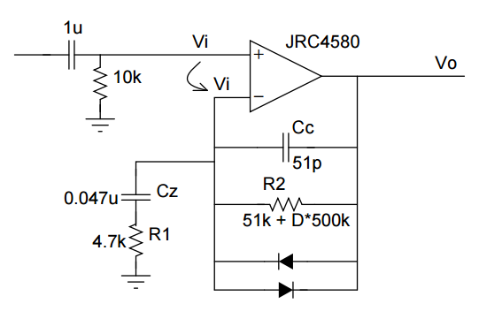
The full schematic is available on the net, for simplicity I will post only the problematic part.
Remove 1u-10k network, Cc on the feedback and the diodes. Also consider D is varying from 0.0 to 1.0.
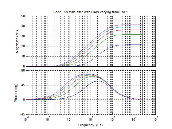
This is a non inverting amplifier with an high pass characteristic (shelving). More precisely this is a first order
transfer function, and can be discretized in the following way
R2 = 51000 + 500000*D;
a1 = (R1 + R2) * Cz * 2 * Fs;
a2 = R1 * Cz * 2 * Fs;
B0 = (1 + a1) / (1 + a2)
B1 = (1 - a1) / (1 + a2)
A1 = (1 - a2) / (1 + a2)
tf1z = (B0+B1*(z^-1))/(1+(A1*(z^-1)));
with Fs=48kHz
My problem is that this filter has a tremendous gain and coefficients rapidly overflow 5.23 fixed point dynamic.
For example with D=0 you have
B0 = 11.3624;
B1 = -11.2724;
A1 = -0.9099;
but just with D=0.25
B0 = 36.7605
B1 = -36.6704
A1 = -0.9099
Any idea?
Thanks
Hello Massimo,
Now I will start this by saying that I am not the worlds expert in analyzing analog circuits and realizing them in a DSP. So others on the forum please interject.
I suspect that what you are running into is that this circuit is supposed to have tons of gain and it supposed to clip and distort! I am wondering where the circuit came out of? A Big Muff distortion pedal? So it is supposed to easily clip but in the analog world when the circuit goes non-linear other factors come in to change the model per-se. The power rails will sag and limit to make it not a true square wave and other factors to alter the spectral content.
So I think you will have to model this in SigmaStudio a bit differently. I am not sure you are aware of this but in the toolbox for the ADAU1701 you will find some non-linear Processors and in there are some clippers. These will clip in a much more controlled way then just overrunning the digital headroom of the DSP.
This circuit you have shown will be linear for small low level signals, but not super clean, then it will start clipping. So try using the data driven clipper or perhaps just setting a threshold on the cubic clipper? Experiment with it.
Let us know how you progress. Please share the schematics as well!
Thanks,
Dave T
Hello,
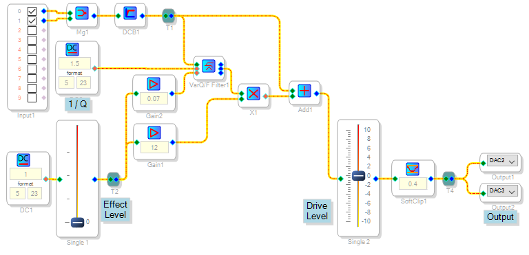
I think David is on to something, it might make more sense to model the effect via stock SIgmaDSP blocks instead of calculating filter coefficients. The arrangement below could make a good starting point:
As you have noted, the original op-amp circuit has a shelf at about 750 Hz, with variable gain and a diode clipper. As the parameter D is increased, ultimate gain at 750 Hz and above increases faster than the gain at lower frequencies. My SigmaDSP version uses the state-variable filter and multiplier to simultaneously adjust gain and frequency response, thus providing a roughly similar function. The cubic clipper provides the soft-clipping distortion characteristic of overdriven vacuum tubes.
Best regards,
Bob
Hi, I quickly understand that this subject of study is too specific, so I tried to solve it by myself. Thank you for
your contribution Bob and Dave T.
The answer for my question is "no you can't have so much gain in a single biquad cell" so I can't
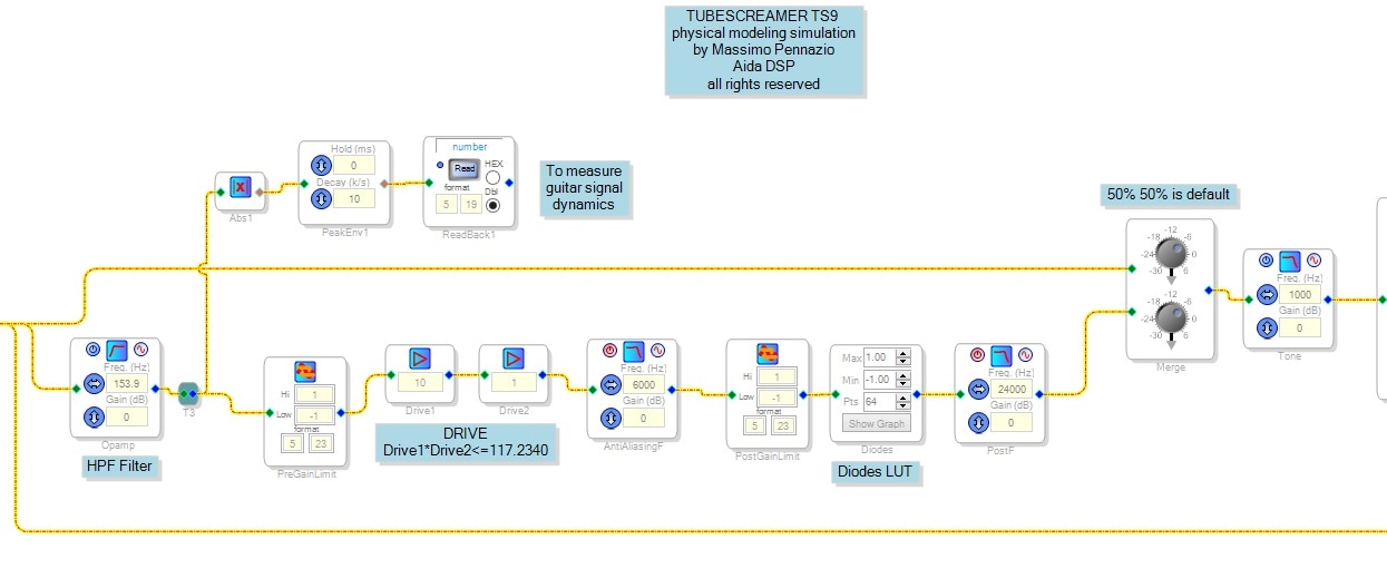
implement my circuit this way, as Bob stated. But the point is I don't really need to implement such a transfer function. Let's write the continuous transfer function of the analog circuit:
Vout/Vin = s*R2 / (R1*(s + 1/(R1*Cz))) + 1;
I can rewrite it in this way
Vout = Vin * tf + Vin
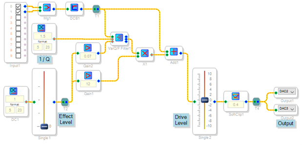
this is very important from Sigma Studio's point of view, since basically here you understand you must sum
input signal with processed signal.
tf can be further analyzed in this way: the static gain k is R2/R1 and there is a zero in the origin and a pole
in 967.1180 rad/sec -> 153.9216 Hz. This is a simple low pass filter with zero gain and corner frequency of 153.9216 Hz.
The non-linear part is the most difficult since you must write the differential equation and solve it to find clipping
curve introduced by diodes. I've done it with the help of Matlab and implemented in Sigma Studio with a LUT.
Finally, this is my schematic. The project is completed with an Arduino Sketch which programs the DSP and changes its parameters in real-time.
There is another question, I wish it could exist an oversampling function for the elaboration of non-linearities in Sigma Studio. Maybe a dedicaded post for it.
Here you can find the Github folder with all the material and of course any contribution is welcomed!
Please log in to reply.