1452 SPDIF Input component missing
I am unable to locate the sp/dif input in the latest Sigma Studio beta release with the 1452 MINIZ evaluation board. Is this a known bug? For what it's worth, the schematic terminal seems also to be missing.
Thanks,
Andreas
I think the only way to access SPDIF input is to wire it to ASRC and the use corresponding ASRC IN signals to process audio from the SPDIF.
Hi Andreas.
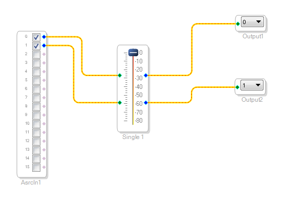
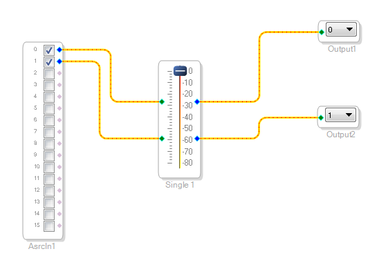
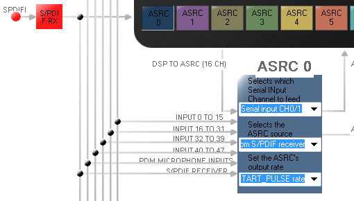
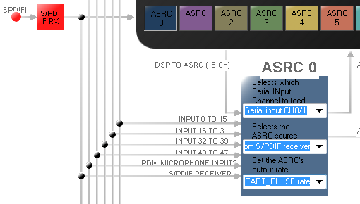
Anton is correct. It looks like for the ADAU144x we provide a SPIDIF input, but for the ADAU1452 we do not. Typical use case is to sample rate convert the SPDIF input and synchronize to START PULSE or output serial port LRCLKs. For example, in the SigmaStudio setup we have SPDIF connected to ASRC0, then our schematic and register configuration "ROUTING_MATRIX" tab are shown below.
Attached is a simple audio passthrough project for the eval board that will pass AD1938 ADC0 data throught the SPDIF outputs/inputs back to the AD1938 DAC0. This uses ASRC0 and will synchronize and convert the SPDIF audio stream to the DSP core processing rate.
Note that the project is is only passing "synchonous" 48kHz data through the SPDIF RX, but I can use the same project to pass 44.1 kHz SPDIF audio data out to the AD1938 DACs at 48 kHz if I disconnect the SPDIF TX and then connect the optical cable to my SPDIF/USB PC dongle.
-JT
Thank you John,
I was hoping for there being a different solution, one that avoids going through the SRC module. For my application I require bit identical pass through and very low latency. I'm afraid that the ASRC will compromise both. Also I don't quite understand why such a simple object like the SPDIF input is not implemented. It might not be the ideal way to approach most of the problems, but it's still useful in certain situations.
Cheers,
Andreas
Hello Andreas,
I read this post and thought I would inject a little more detail.
You can route the SPDIF input directly out to a serial output port without using an ASRC but also without using the DSP. Obviously this is of limited use but it is possible.
The reason you have to go through an ASRC has to do with clocking. You would not want to make the SPDIF input signal be the master and drive all of the DSP clocks. By using the ASRC you will allow the DSP to run on its own clock and the SPDIF clocks can come and go and drift on their own.
Since there are only 8 stereo ASRCs it is best to leave it up to the user to choose how they want them used. It would be wasteful to dedicate an ASRC only for an SPDIF input that will not always be needed. If there were a dedicated ASRC then it would make sense to have an SPDIF Input object to drop into a schematic. Since that is not the case then we leave it up to you to route the SPDIF signal to the ASRC then we have the ASRC object that you drop into the schematic where the ASRC output signals are available.
Thanks,
Dave T
This question has been assumed as answered either offline via email or with a multi-part answer. This question has now been closed out. If you have an inquiry related to this topic please post a new question in the applicable product forum.
Thank you,
EZ Admin
Please log in to reply.