Microphone Ducking music
Hello,
Is there a preferred Dynamics Processor block to use when ducking inputs triggered from a microphone source? I am trying to set up a scenario where a paging microphone lowers all the other inputs. Thanks.
adau144x
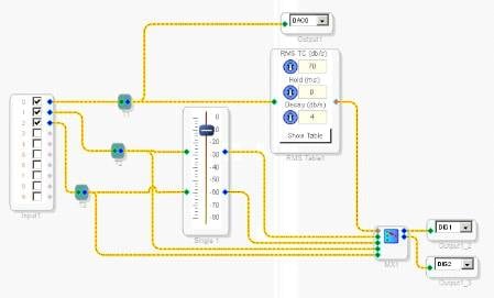
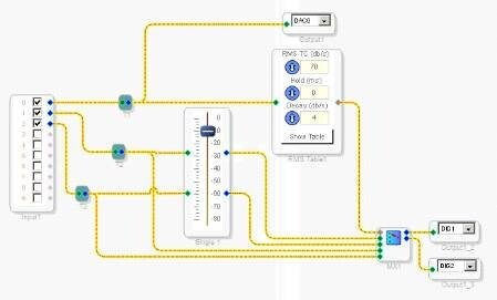
From my understanding of how ducking operates, you do not want to use one of the dynamic processors. The dyanamics processors operate in a way to compress the dynamic range of a signal. This in no way seems to effect any additional audio data lines. I have not tested out the following code but it might give you some ideas of how to do what you want:
You use the RMS Table to detect a level and then you have it select one mux path or the other. One of the mux paths has no attenuation while the other has a volume control attenuating the signal. Therefore you should get attenuation on Input1 and Input2 while Input0 contains a signal greater than your selected value in the table. Again I have not tested this but I belive it should work.
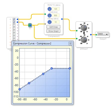
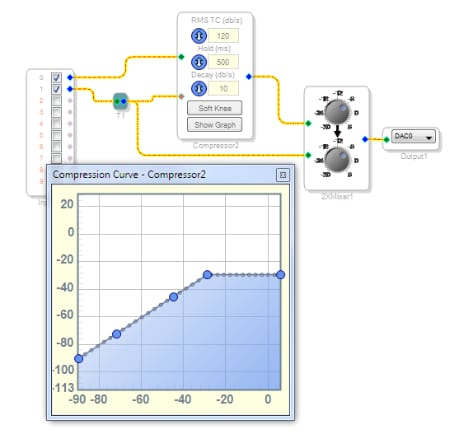
This can be easily done with a standard dynamics processor block with an external detector input. In this sort of design, you just use the audio from the microphone at the detector input (red pin) of the dynamics processor, and the other audio that you want to attenuate is connected to the audio inputs (green pins) of the dynamics processor. Then, when a signal is present on the mic inputs, it can apply attenuation (compression) to the other signals. A quick example of this is shown below.
Here, the microphone signal is on input 1 and the other audio is on input 0. I've set the curve to limit the audio to -30 dB any time there is a signal on the microphone path greater than -30 dB. Of course, you will want to experiment with different settings for this curve to find one that works for your application. I've also set the compressor's hold time to much longer (500 ms) than the default. This is so the gain of the main audio signal doesn't fluctuate up and down between words or phrases on the microphone signal.
That is very interesting Jerad I didn't realize that "orange" inputs could take in raw audio until I saw your post (and reread the help). I looks like your solution is a bit more elegant than my own. Which axis of the compresson curve is the control signal level on the graph?
The x-axis is the detector input's signal level and the y-axis is the output signal level.
Thanks guys. This is the way that I have it designed currently. I was wondering if there were any particular compressor/limiter blocks that would be better suited for this. Thanks again.
Hi tonemeister. I think the RMS compressors would be better suited for this because their detection signal is based on the average signal level, not the peak signal level, and that's a more reliable indicator of audio power. That's the best way to get the expected results in an application like this.
This question has been assumed as answered either offline via email or with a multi-part answer. This question has now been closed out. If you have an inquiry related to this topic please post a new question in the applicable product forum.
Thank you,
EZ Admin
Please log in to reply.